Methods & apparatus for magnetic resonance imaging

a magnetic resonance imaging and method technology, applied in the field of methods and apparatus for magnetic resonance imaging, can solve the problems of long overall scan time and motion sensitivity, complex computer processing requirements, and patient expectation of remaining, and achieve the effect of reducing image acquisition tim

Inactive Publication Date: 2005-12-27
UNIV OF SHEFFIELD AT WESTERN BANK THE
View PDF7 Cites 51 Cited by
  • Summary
  • Abstract
  • Description
  • Claims
  • Application Information

AI Technical Summary

Benefits of technology

[0035]One object of the present invention is to provide an improved parallel MRI method and apparatus to enable multi-slice magnetic resonance images to be obtained substantially simultaneously whilst decreasing image acquisition time as compared with existing MRI systems that employ a B1 sensitivity encoding technique such as SMASH or SENSE.

Problems solved by technology

In the known MR imaging approach described above there is therefore a problem in that if more than one frequency range is excited at a given time the detector 107 receives signals which the central processing unit 110 is unable to unscramble.
These methods have been found to result in longer overall scan times and motion sensitivity.
By motion sensitivity it is meant, in a medical imaging context for example, patient movement, since it is difficult in many circumstances to expect a patient to remain still for a sufficient time period whilst a given image is being acquired.
Larkman's method concerns use of multicoil arrays for separation of signals from multiple slices excited simultaneously and although it permits simultaneous slice-imaging it utilizes a number of RF coils and a number of expensive receiver channels resulting in complex computer processing requirements.
Weaver's method uses a slice selection gradient applied during readout to separate slices with frequency over sampling, but the method suffers from severe image distortion and blurring artefact due to oblique angulation of the image readout gradient.
However the method disclosed does not incorporate any other form of parallel imaging.

Method used


Image

  • Methods & apparatus for magnetic resonance imaging
  • Methods & apparatus for magnetic resonance imaging
  • Methods & apparatus for magnetic resonance imaging

Examples


Embodiment Construction

[0243]There will now be described by way of example the best mode contemplated by the inventors for carrying out the invention. In the following description numerous specific details are set forth in order to provide a thorough understanding of the present invention. It will be apparent however, to one skilled in the art, that the present invention maybe practiced without limitation to these specific details. In other instances, well known methods and structures have not been described in detail so as not to unnecessarily obscure the present invention.

[0244](1) One-Dimensional MAMBA Magnetic Resonance Imaging

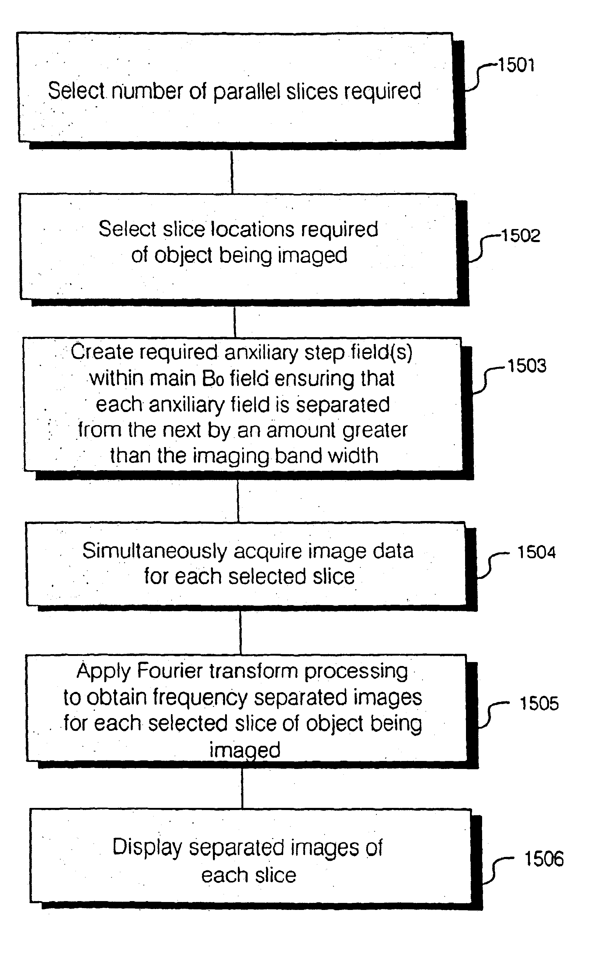
[0245]In order to overcome the problem of presenting image frequency encode aliasing, the inventors of the present invention have found that parallel simultaneous image slices maybe obtained using stepped auxiliary B0 fields within the main B0 magnetic field. The auxiliary fields are required to be uniform B0 regions and are generated using auxiliary field coils. Each of these u...


PUM


Abstract

A parallel magnetic resonance imaging (MRI) apparatus configurable to image a physical entity comprises:a main magnetic flux source for providing a uniform fixed magnetic field, B0;an RF array system comprising a plurality of RF coils and receivers, said RF system configured for:generating rotating RF excitation magnetic fields B1; andreceiving RF signals due to precessing nuclear magnetization on multiple spatially distinct radio frequency coils and associated receiver channels, said RF system being configured to operate in accordance with a B1 sensitivity encoding technique;a control processor for controlling imaging functionality, collecting image data and effecting data processing of the captured image data the control processor being configured with post processing capability for the B1 sensitivity encoding technique;an image display means for displaying processed image data as resultant images; andan auxiliary magnetic field means capable of producing at least one auxiliary uniform B0 step magnetic field imaging region within the main B0 magnetic field;wherein:the auxiliary magnetic field, means is configured to operate in combination with the RF coil system and the B1 sensitivity encoding technique, the imaging apparatus thereby providing faster image acquisition than that attributed to the speed up factor provided solely by the B1 sensitivity encoding technique.The invention also includes a method of imaging using this apparatus.Furthermore, the invention also includes a method and apparatus for three-dimensional MR imaging using a 1D Multiple Acquisition Micro B0 array coupled with a 2D Multiple Acquisition Micro B0 array.

Description

[0001]This is a continuation-in-part of U.S. patent application Ser. No. 10 / 195,756, filed Jul. 15, 2002 and claims priority on GB 0211516.0 filed May 20, 2002.FIELD OF THE INVENTION[0002]The present invention relates to methods and apparatus for magnetic resonance imaging (MRI) of a physical entity. The invention more particularly relates to improved MRI methods and apparatus that provide fast imaging and particularly, but not exclusively the invention relates to parallel MRI and three-dimensional MRI.BACKGROUND TO THE INVENTION[0003]It is known in the field of nuclear magnetic resonance (NMR) imaging that it is desirable to reduce image scan times. In order to generate an NMR signal the net magnetic moment (M) of a sample comprising many nuclei is manipulated with suitable RF pulses. A variety of commonly used pulse sequences are known such as free induction decay (FID), inversion recovery and the well-known spin-echo sequence. In traditional magnetic resonance imaging systems a u...

Claims


Application Information

Patent Timeline
Patent Type & Authority Patents(United States)
IPC IPC(8): G01R33/48G01R33/54
CPCG01R33/445G01R33/4835
Inventor PALEY, MARTYNLEE, KUAN
Owner UNIV OF SHEFFIELD AT WESTERN BANK THE
Why Eureka
Try Eureka