Clock data recovery system

a clock data and clock generator technology, applied in the field of clock data recovery system, can solve the problems of insufficient accuracy of resampled clock related to the incoming data signal stream, varying the gain and bandwidth of the clock data recovery system loop, and not being well predicted, so as to increase the loop bandwidth and the increment of clock generators. the effect of small, fast loop bandwidth

Active Publication Date: 2005-12-27
LENOVO GLOBAL TECH INT LTD
View PDF13 Cites 20 Cited by
  • Summary
  • Abstract
  • Description
  • Claims
  • Application Information

AI Technical Summary

Benefits of technology

[0011]One main advantage of the present invention is that the control loop is correcting any timing offset between the incoming data stream and the clock in an improved fashion. The reason for this improvement lies in the fact that the residual error of a feedback-based control loop is limited to 1 / (1+A), where A is the open-loop gain of the control loop. The higher the gain the smaller is the residual error.
[0012]Additionally an increased gain also increases the loop bandwidth so that an error, i.e. phase difference between a transition of a resampled clock signal and a bit transition of the incoming data stream, is corrected faster. In other words, the smaller the bit transition density, the more aggressively, i.e. using larger increments, the control signal is adjusting the frequency of the clock generator. Thus, the more transitions the incoming data signal stream has per time period, the faster it can adjust the clock generator via the control signal and the smaller the increments for adjusting the clock generator can be. Therefore a larger bandwidth can be achieved. Thus, having a small bit transition density, the gain is set high, and therefore stronger and more aggressive corrections steps are made to readjust the frequency of the clock generator.
[0013]Adjusting the gain of the clock data recovery loop has the same effect as a variable bandwidth which can be implemented e.g. by a low-pass filter. In contrast thereto, a variable gain is easier to implement e.g. by using a variable-gain element.
[0014]Further advantageous embodiments of the inventions are disclosed in the dependent claims.
[0015]In a preferred embodiment of the invention the variable gain is increased dependent on a decrease of the bit transition rate, preferably in a manner to provide a constant gain-bandwidth-product. This has the advantage that even at low bit transition rates of the incoming data signal stream an advantageous bandwidth of the clock data recovery system can be maintained, resulting in a quick adjusting of the resampled clock signal. A further advantage is that the preferred relationship is easy to implement while being very effective in adapting the clock signal generation to the bit transition rate.
[0016]According to another preferred embodiment of the invention, the loop controller includes a low-pass filter and a variable-gain element. The low-pass filter can be connected with the phase detector to low-pass filter the phase difference signal and to adjust the bandwidth of the clock data recovery system. The variable-gain element is operable to amplify the low-pass filtered phase difference signal dependent upon the variable-gain to obtain the control signal. This embodiment has the advantage that bandwidth and gain can be set up separately wherein the bandwidth of the system is determined by the low-pass filter and the gain is determined by the variable-gain element.

Problems solved by technology

Therefore the gain and the bandwidth of the clock data recovery system loop is also varying and not well predictable.
The disadvantage of that clock-data-recovery system lies in an insufficient accuracy of the resampled clock related to the incoming data signal stream, especially when the bit transition rate of the incoming signal stream is low.
This may result in a continuous restarting of adjusting the frequency of the phase lock loop onto the incoming data signal stream.

Method used


Image

  • Clock data recovery system
  • Clock data recovery system
  • Clock data recovery system

Examples


Embodiment Construction

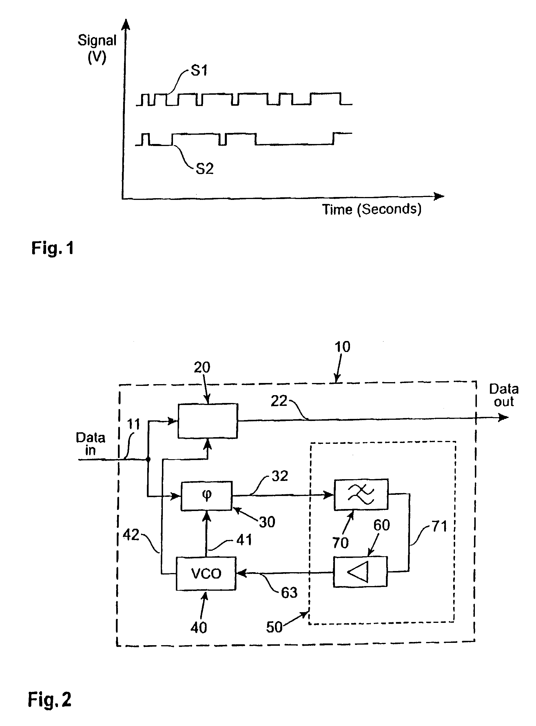
[0025]During the serial transmission of random data streams the number of data transitions from one to zero and zero to one respectively are not constant when counted over a given number of transmitted bits. This results in a variation of the bit transition density of the data signal stream. In FIG. 1 two different data signal streams are depicted. A first data signal stream S1 shows a data signal that has a larger bit transition density than a second data signal stream S2. Both data signal streams S1, S2 provide the same number of transmitted bits per time period although in the second data signal stream S2 more non-changing bits in a row occur than in the first data signal S1. For both data signal streams S1, S2 a clock data recovery system is resampling a clock signal with the same frequency.

[0026]These different types of signal data streams result from the type of line code that is used. Typical line codes may be e.g. 8B10B, scrambling, 10 Gb Ethernet etc. The different type of ...


PUM


Abstract

A clock data recovery system is provided for resampling a clock signal according to an incoming data signal stream. It comprises a clock generator for generating said clock signal wherein one of the frequency and phase of that clock signal is dependent upon a control signal. It is further provided a phase detector operable to detect the phase difference between said clock signal and said incoming data signal stream and is operable to generate a phase difference signal. A loop controller has a variable-gain and is operable to control said clock generator by generating said control signal. That control signal is dependent in said phase difference signal and that variable-gain. The variable-gain is dependent upon a transition rate of the incoming data signal stream. The loop controller can comprise a low-pass filter to generate from the phase difference signal a low-pass filered phase signal and to adjust the bandwidth of the clock data recovery system. The loop controller further can comprise a variable-gain element to amplify the filtered signal in accordance with a received bit transition rate provided by a bit transition detector and a density calculator.

Description

[0001]The present invention is related to a clock data recovery system especially to a clock data recovery system with an adjustable gain.BACKGROUND OF THE INVENTION[0002]During the serial transmission of random data streams the number of data transitions from one to zero and zero to one, respectively, is not constant when counted over a given number of transmitted bits. This results in a variation of the bit transition density, which depends on what type of line code is used, e.g. 8B10B, scrambling, 10 Gb Ethernet etc. The bit-transition-density-variation ranges from three guaranteed transitions in ten bits to one transition only for more than 100 transmitted bits.[0003]To resample a clock on which the data stream is based, clock data recovery systems are used. Conventional clock data recovery systems are generating a control loop error signal from the measurement of timing of when a transition in the incoming data signal stream occurs. This information is used to speed up or slow ...

Claims


Application Information

Patent Timeline
Patent Type & Authority Patents(United States)
IPC IPC(8): H03K5/1534H03L7/093H04L7/033
CPCH03K5/1534H03L7/093H04L7/033
Inventor SCHMATZ, MARTINMENOFLI, CHRISTIANMORF, THOMAS
Owner LENOVO GLOBAL TECH INT LTD
Why Eureka
Try Eureka