Method of automatically calibrating electronic controls in a mass spectrometer

a mass spectrometer and automatic calibration technology, applied in the field of mass spectrometers, can solve the problems of affecting the performance of mass analysis, reducing and not allowing the required precision and stability of signals to be maintained, so as to reduce the requirement for initial and periodic manual calibration and increase the accuracy of mass analysis

Active Publication Date: 2006-01-03
FLIR DETECTION
View PDF15 Cites 17 Cited by
  • Summary
  • Abstract
  • Description
  • Claims
  • Application Information

AI Technical Summary

Benefits of technology

[0015]An advantage of the present invention is that the mass spectrometer includes a circuit for controlling an output signal for a component. The circuit adjusts the output signal to achieve a required precision associated with the output signal. Thus, the accuracy of the mass analysis is increased and the requirement for initial and periodic manual calibration is reduced.
[0016]Another advantage is that the mass spectrometer includes a circuit that monitors the output signal and predicts the level of precision that may be achieved and the likelihood of component or circuit degradation or impending failure of the component or circuit associated with the output signal. Thus, the reliability of the mass spectrometer may be monitored by the user.

Problems solved by technology

Practical limitations to the electronic components used to generate the signals may cause enough inherent instability, imprecision, and degradation over time to affect the performance of the mass analysis.
However, signal calibration before analysis and periodic monitoring of the quality of the data may not allow the required precision and stability of the signals to be maintained.
Additionally, a user may not detect component degradation over time that is suggestive of an impending failure of the component.

Method used


Image

  • Method of automatically calibrating electronic controls in a mass spectrometer
  • Method of automatically calibrating electronic controls in a mass spectrometer
  • Method of automatically calibrating electronic controls in a mass spectrometer

Examples


Embodiment Construction

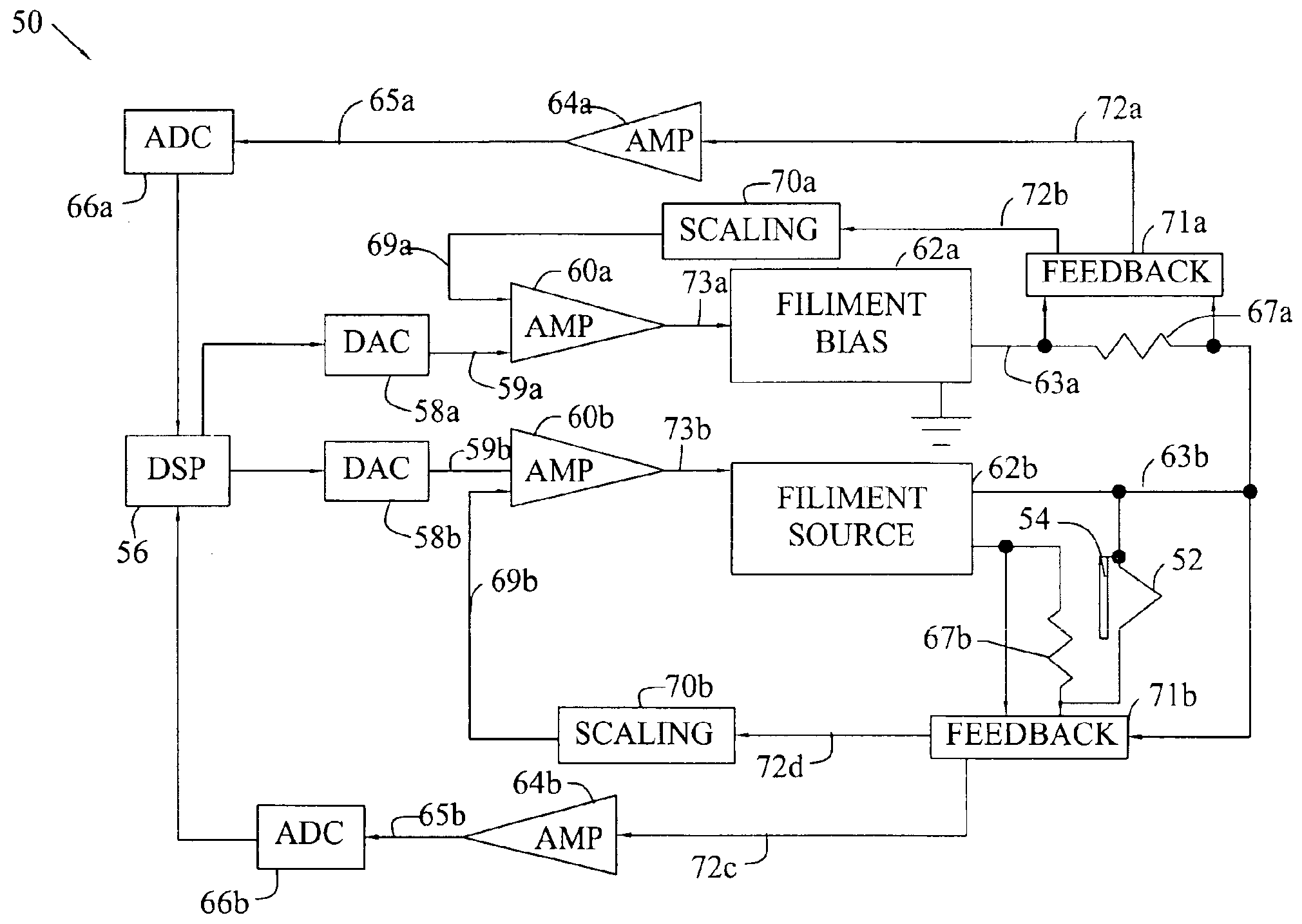
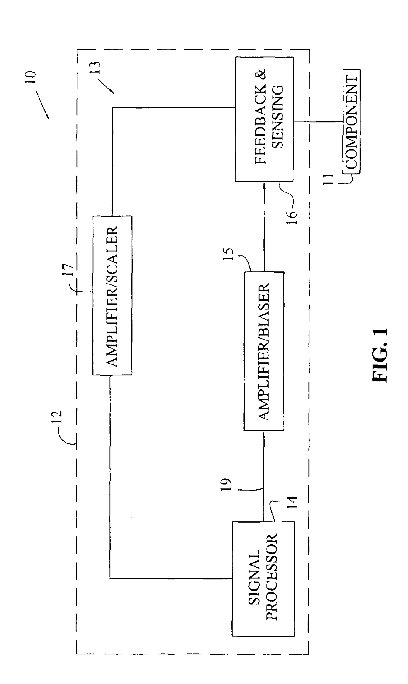
[0028]Referring now to the drawings, and particularly to FIG. 1, there is shown one embodiment of a functional assembly 10 suitable for use in a mass spectrometer of the present invention. Assembly 10 includes a component 11 for performing a mass spectrometry function, such as ionization, ion extraction, ion transportation, ion trapping, ion analysis, or ion detecting, for example. A driving circuit 12 is electrically coupled to and drives component 11. Driving circuit 12 may include a signal generator 13, including a signal processor 14 and an amplifier / biaser 15 for applying an output signal to component 11. A feedback and sensing device 16 senses a voltage and / or a current associated with the output signal applied to component 11. Device 16 then transmits a feedback signal dependent on the sensed voltage and / or current to signal generator 13.

[0029]The feedback signal may be amplified and / or scaled by amplifier / scaler 17 before being input to the signal processor 14. Based on the ...


PUM


Abstract

The present invention provides methods and electronic circuits for a chemical analyzer, for example, a mass spectrometer, which provide generated signals that are maintained to a required level of precision. A user may specify the required precision for the signals which operate the spectrometer and may specify the required precision for the mass analysis, either explicitly or by choosing a predefined configuration. The spectrometer will then generate the signals to the required precision despite changes in operating conditions, environmental conditions, component aging and degradation, or other nonfailure effects that otherwise affect analyzer calibration and signal output. The electronic circuits incorporate signal monitoring to maintain closed-loop signal control. The closed-loop control includes a feedback path which may include discrete components and may include software enabling a processor to adjust the generated signals to maintain the required precision of the signals and analysis. Further, the spectrometer may monitor signals and analyze and store data in order to predict future performance, including precision, analysis limitations, impending component degradation or failure, or another parameter associated with a component or signal of the spectrometer. Specifically, a range for a particular parameter may be specified and a indication provided to a user when the parameter exceeds the specified range.

Description

[0001]This application claims the benefit of U.S. Provisional Patent Application No. 60 / 500,545 filed on Sep. 5, 2003.BACKGROUND OF THE INVENTION[0002]1. Field of the Invention[0003]The present invention relates generally to the field of mass spectrometers and, more specifically, to mass spectrometers that include electronic control circuits for generating and adjusting electronic signals.[0004]2. Description of the Related Art[0005]A particular type of mass spectrometers, an ion trap, includes electrodes for analysis and subsequent detection and measurement of ions having various mass-to-charge ratios. The components of ion traps typically include two grounded end-cap electrodes sandwiching a ring electrode to which a radio frequency (RF) signal is applied for the trapping of ions, a filament and repeller for producing an electron beam, lens elements for ion focusing in order to transport ions or electrons, and an electron multiplier, channel plate, or other ion detector. Each of t...

Claims


Application Information

Patent Timeline
Patent Type & Authority Patents(United States)
IPC IPC(8): H01J49/00H01J49/04H01J49/02H01J49/42
CPCH01J49/0009H01J49/022H01J49/0027
Inventor KNECHT, BRENT A.PATTERSON, GARTH E.
Owner FLIR DETECTION
Why Eureka
Try Eureka