Moving magnet actuator for providing haptic feedback

a moving magnet actuator and haptic feedback technology, which is applied in the direction of mechanical control devices, instruments, manual control with single controlling member, etc., can solve the problems of inability to significantly vary the vibrations of these implementations, limited current implementations of vibrotactile feedback, and inability to produce low-bandwidth vibrations, etc., to achieve more compelling force effects, high magnitude, and high bandwidth vibrations

Inactive Publication Date: 2006-01-03
IMMERSION CORPORATION
View PDF87 Cites 211 Cited by
  • Summary
  • Abstract
  • Description
  • Claims
  • Application Information

AI Technical Summary

Benefits of technology

[0007]The present invention is directed to moving magnet actuators that provide haptic sensations in a haptic feedback device that is interfaced with a host computer. The present invention provides actuators that output high magnitude, high bandwidth vibrations for more compelling force effects.
[0011]The present invention advantageously provides an actuator for a haptic feedback device that can output high quality vibrotactile sensations. Both the frequency and amplitude of the vibrations can be controlled using bi-directional control, and features such as the elastic material and flexures contribute to a high quality and high bandwidth vibration force output.

Problems solved by technology

These current implementations of vibrotactile feedback, however, tend to be limited and produce low-bandwidth vibrations that tend to all feel the same, regardless of the different events and signals used to command them.
The vibrations that these implementations produce also cannot be significantly varied, thus severely limiting the force feedback effects which can be experienced by a user of the device.

Method used


Image

  • Moving magnet actuator for providing haptic feedback
  • Moving magnet actuator for providing haptic feedback
  • Moving magnet actuator for providing haptic feedback

Examples


Embodiment Construction

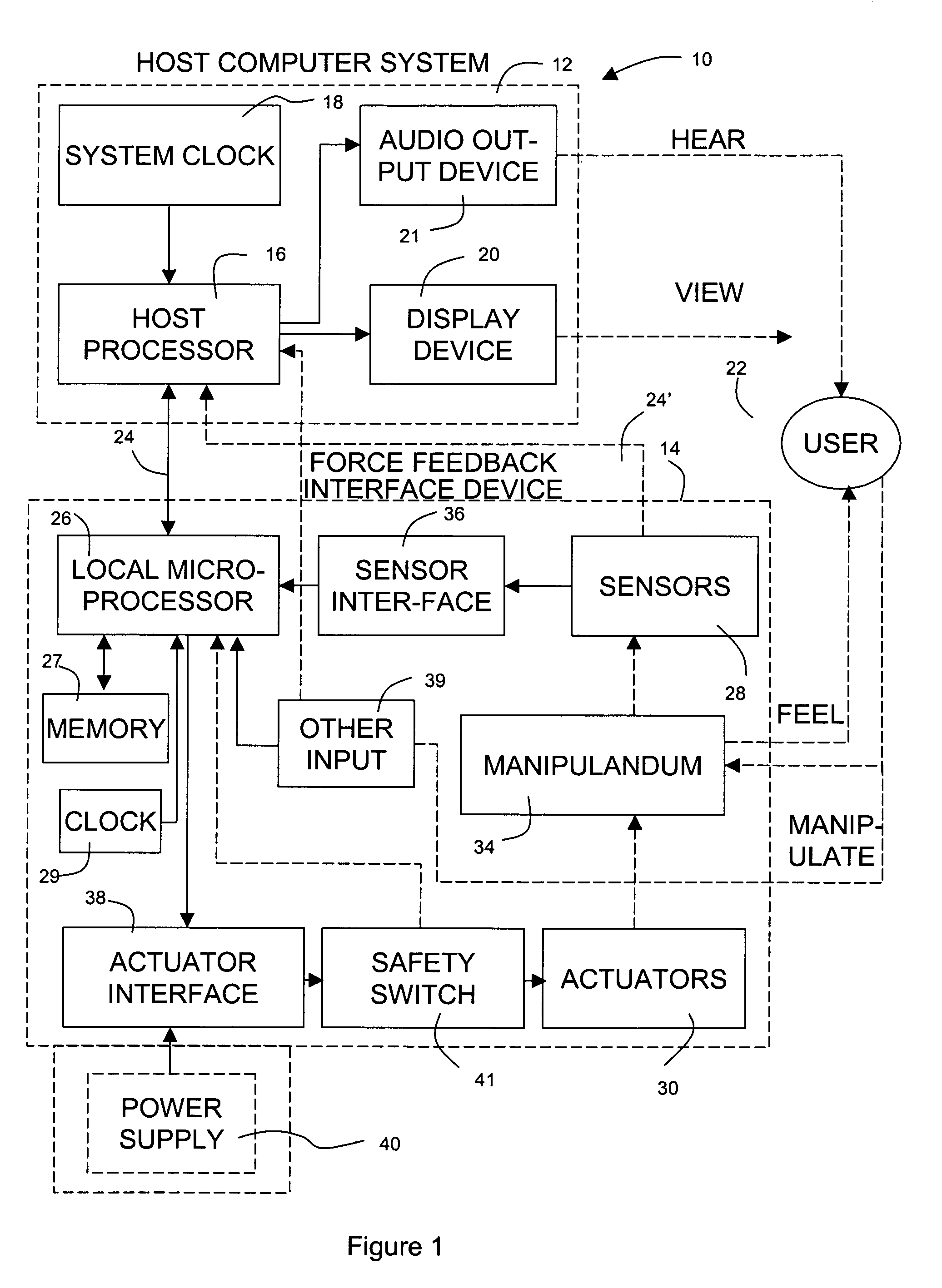
[0018]FIG. 1 is a block diagram illustrating a force feedback interface system 10 for use with the present invention controlled by a host computer system. Interface system 10 includes a host computer system 12 and an interface device 14.

[0019]Host computer system 12 can be any of a variety of computer systems, such as a home video game systems (game console), e.g. systems available from Nintendo, Sega, or Sony. Other types of computers may also be used, such as a personal computer (PC, Macintosh, etc.), a television “set top box” or a “network computer,” a workstation, a portable and / or handheld game device or computer, etc. Host computer system 12 preferably implements a host application program with which a user 22 is interacting via peripherals and interface device 14. For example, the host application program can be a video or computer game, medical simulation, scientific analysis program, operating system, graphical user interface, or other application program that utilizes for...


PUM


Abstract

A moving magnet actuator for providing haptic feedback. The actuator includes a grounded core member, a coil is wrapped around a central projection of the core member, and a magnet head positioned so as to provide a gap between the core member and the magnet head. The magnet head is moved in a degree of freedom based on an electromagnetic force caused by a current flowed through the coil. An elastic material, such as foam, is positioned in the gap between the magnet head and the core member, where the elastic material is compressed and sheared when the magnet head moves and substantially prevents movement of the magnet head past a range limit that is based on the compressibility and shear factor of the material. Flexible members can also be provided between the magnet head and the ground member, where the flexible members flex to allow the magnet head to move, provide a centering spring force to the magnet head, and limit the motion of the magnet head.

Description

CROSS REFERENCE TO RELATED APPLICATIONS[0001]This application claims priority to U.S. Provisional Application No. 60 / 142,155, filed Jul. 1, 1999, entitled, “Providing Vibration Forces in Force Feedback Devices,” and which is incorporated by reference herein.[0002]This invention was made with government support under Contract Number N00014-98-C-0220, awarded by the Office of Naval Research. The government has certain rights in this invention.BACKGROUND OF THE INVENTION[0003]The present invention relates generally to producing forces in force feedback interface devices, and more particularly to the output and control of vibrations and similar force sensations from actuators in a force feedback interface device.[0004]Using an interface device, a user can interact with an environment displayed by a computer system to perform functions and tasks on the computer, such as playing a game, experiencing a simulation or virtual reality environment, using a computer aided design system, operati...

Claims


Application Information

Patent Timeline
Patent Type & Authority Patents(United States)
IPC IPC(8): G09G5/00
CPCG06F3/016G05G2009/04766
Inventor SHAHOIAN, ERIK J.
Owner IMMERSION CORPORATION
Why Eureka
Try Eureka