Dielectric mold for uniform heating and molding of polymers and composites in microwave ovens

a technology of microwave oven and polymer, which is applied in the field of microwave processing, can solve the problems of reduced thermal variation, poor thermal conductivity of polymers, and reduced thermal variation, and achieve the effect of reducing microwave energy losses and reducing the total heat energy accumulated in molds

Inactive Publication Date: 2006-01-10
AKOPYAN RAZMIK L
View PDF56 Cites 34 Cited by
  • Summary
  • Abstract
  • Description
  • Claims
  • Application Information

AI Technical Summary

Problems solved by technology

The overall distribution of electromagnetic energy is not uniform throughout the microwave cavity or the work material resulting in high and low energy field areas.
Such hot and cold spots can be observed in household microwave ovens and are tolerated for food applications, because relatively high thermal conductivity of water containing food results in reductions of the thermal variations established due to non-uniform heating.
But this is not the case for high performance polymers since most of these polymers exhibit very poor thermal conductivity.
Any attempt to heat the polymer work material in a conventional microwave oven without specially designed molds will lead to overheating or burns of the polymer in some places while in other its places will be under heated or cured.
While these methods provide some improvement, it has not been possible to achieve desired uniformity of temperature field in the work material.
However, operation of microwave ovens at a frequency of 28 GHz is considered too expensive and is out of the permitted frequency range.
A disadvantage of such a technique is that presently the maximum microwave power available does not exceed 500 W, and VFM ovens are not generally commercially available.
Experimentally it has been shown that regions with undesirably wide variations of temperature arise in the load whenever an attempt is made to increase the size of workload assembly and quantity of heating ceramic components.
Another drawback of this method relates to the working condition of the microwave generator.
The presence of tall conducting metal rings having a total height comparable with the dimension of microwave cavity may cause significant reflection of microwave energy toward the generator and may affect its safety during operation.
Such a method cannot be used for uniform heating of thick or massive work-pieces and will face the same challenges as conventional methods employing infrared radiation.

Method used


Image

  • Dielectric mold for uniform heating and molding of polymers and composites in microwave ovens
  • Dielectric mold for uniform heating and molding of polymers and composites in microwave ovens
  • Dielectric mold for uniform heating and molding of polymers and composites in microwave ovens

Examples


example 1

[0067]A mold was designed for PVC (polyvinyl chloride) in accordance with the techniques described above. Pellets of PVC were poured into the cavity defined by the inner mold layer which was formed from SiC—Al2O3. The mold and PVC pellets were then heated in a uniform RF field at the frequency f 27.12 MHz for approximately 2 minutes under pressure of approximately 30 psi. The cavity was 2.7 inches in diameter and 1.5 inches deep. The uniformity of heating of the PVC pellets to form a work piece was examined visually since the molded PVC part was transparent. The obtained molded samples demonstrated uniformity of heating.

example 2

[0068]A mold was designed for TORLON thermoplastic and tested as in Example 1. Instead of pellets, two solid disks of TORLON, grade 4301, 2.7 inches in diameter and 0.5 inches thick were used for molding. After heating for approximately 3 minutes in an RF field, both disks were melted forming a uniformly solid disk of 1 inch thickness. Molding was performed at a pressure of approximately 30 psi.

example 3

[0069]A mold was designed for a low loss composite structure containing thermoset silicon resin and fiberglass fabric. About 100 layers of fiberglass fabric were covered by a thin layer of silicon resin grade V-340 made by Rhodia. This composite structure was placed into the mold cavity of 2.7 inches in diameter and heated by RF energy as in Examples 1 and 2. Curing temperature exceeded 150° F. (Fahrenheit) and after 10 minutes of heating time, the composite structure was completely cured. The cured sample had a thickness of approximately 1 inch. Curing of such structure by conventional means would require several hours since silicon-fiberglass composites exhibit a very low thermal conductivity. This test was made to demonstrate the applicability of RF / microwave processing to composite structures.


PUM

PropertyMeasurementUnit
radio frequenciesaaaaaaaaaa
sizeaaaaaaaaaa
microwave frequenciesaaaaaaaaaa

Abstract

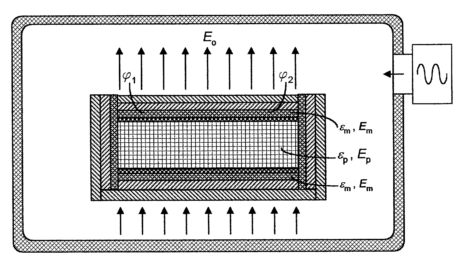
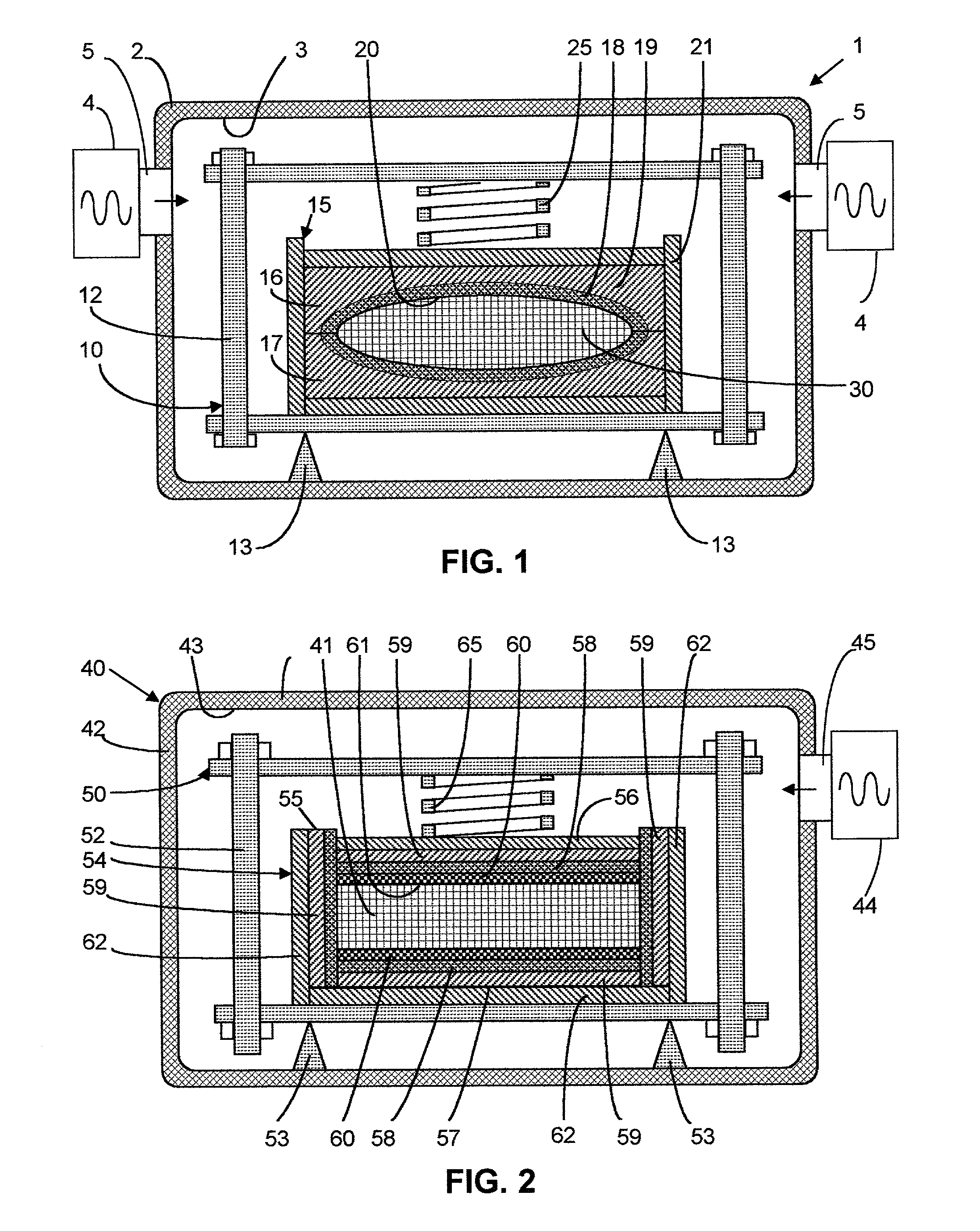
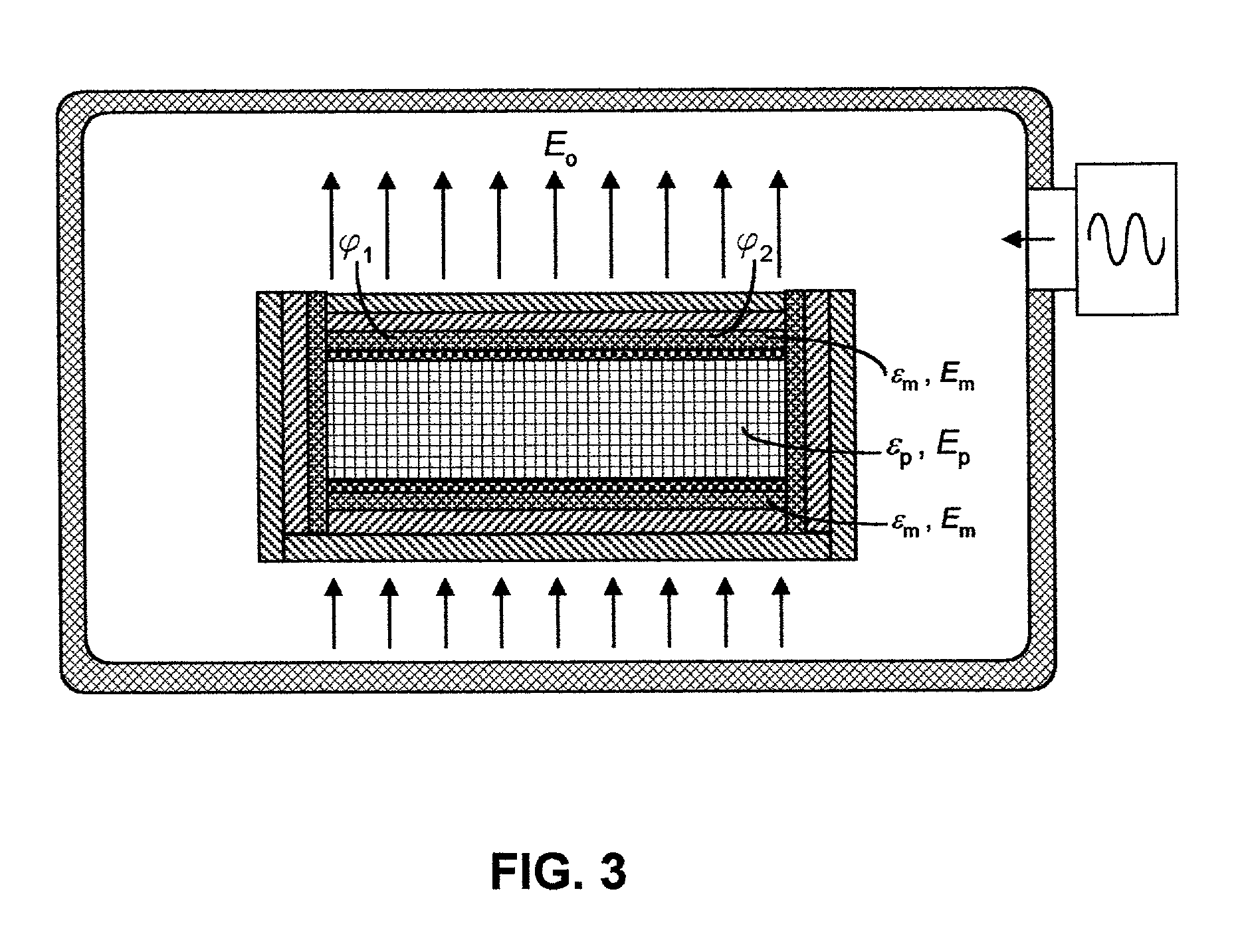
A mold for uniformly heating working material to form a workpiece using a microwave oven. Uniform heating of a workpiece of variable thickness may be obtainied in a microwave oven with a uniform electric field in its cavity if the mold material is selected to have a dielectric constant and a thermosensitivity equal to that of the working material. The thermosensitivity of a material is its dissipation factor divided by the product of its density and specific heat. Uniform heating of a uniformly thick workpiece can be obtained in a conventional microwave by selecting the mold material to have a relative thermosensitivity equal to that of the working material. The relative thermosensitivity of a material is its dissipation factor divided by the product of its dielectric constant, density, and specific heat.

Description

BACKGROUND OF THE INVENTION[0001]This invention relates generally to microwave processing of high performance polymers, composites and the sintering of ceramics, and more specifically to the design of molds for processing of such materials including the selection or modification of materials to form the mold to provide for uniform heating of polymers, composites or ceramics by microwave energy.[0002]Efforts to use radio frequency (RF) or microwave processing of polymers and composites has been pursued over the past few decades and yields substantial advantages. In contrast to conventional thermal treatments, the advantages of RF and microwave processing include rapid volumetric heating, avoidance of overheating at the surface, reduced processing time and reduced degradation of the processed polymers. RF dielectric heating may be efficient in applications where uniform volumetric heating is required for workpieces of large volumes and dimensions. RF heating has found a wide range of ...

Claims


Application Information

Patent Timeline
Patent Type & Authority Patents(United States)
IPC IPC(8): B29C33/40B29C33/38B29C35/08
CPCB29C33/3828B29C35/0805B29C33/3835B29C2035/0855
Inventor AKOPYAN, RAZMIK L.
Owner AKOPYAN RAZMIK L
Why Eureka
Try Eureka