
Mass spectrometer and methods of increasing dispersion between ion beams

a mass spectrometer and ion beam technology, applied in the direction of instruments, particle separator tube details, separation processes, etc., can solve the problems of no more than 70% efficiency, high design and construction requirements of scanning mass spectrometers, and no more than 70% background counts of channeltron multipliers, etc., to achieve low noise detectors and high efficiency

Inactive Publication Date: 2006-01-10
BATTELLE ENERGY ALLIANCE LLC
View PDF4 Cites 6 Cited by
  • Summary
  • Abstract
  • Description
  • Claims
  • Application Information

AI Technical Summary

Benefits of technology

The invention relates to a mass spectrometer with a high dispersion mass analyzer that can accommodate full-sized discrete dynode multipliers for simultaneously measuring adjacent isotopes. The mass spectrometer has a magnetic sector and an electrostatic sector that separates and increases the separation between ion beams. This allows for the simultaneous measurement of multiple isotopes of a sample. The invention also includes a method of increasing the separation between ion beams using the electrostatic sector. The technical effects of the invention include improved accuracy and sensitivity in mass spectrometry and the ability to measure isotopic ratios of elements in a sample simultaneously.

Problems solved by technology

Design and construction of a mass spectrometer with high sensitivity to measure isotope ratios require compromises in design and construction.
Scanning mass spectrometers that can only measure one isotope at a time are at a disadvantage under these circumstances, since the signals from the isotopes of interest may have to be interpolated to obtain isotope ratios.
Such channeltron multipliers have high background counts and no more than 70% efficiency.
The high background counts tend to limit sensitivity.
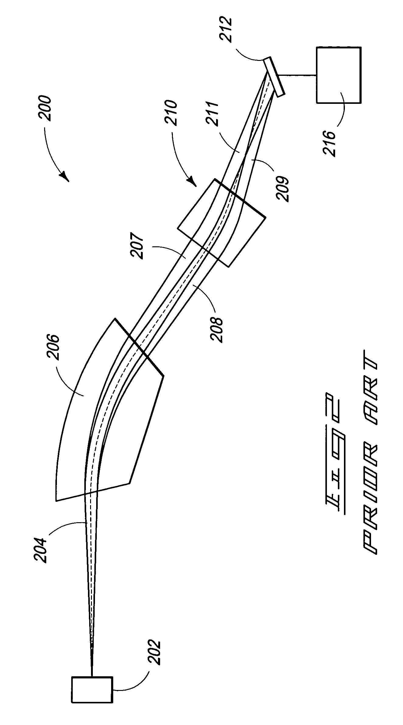
Mass spectrometers made by the above-noted entities do not have sufficient dispersion between adjacent isotopes to accommodate full-sized multipliers that have 100% efficiency and background levels of about 3 counts / minute.
Such instruments operated in the scanning or peak stepping mode and were not practical to set up to collect an entire U or Pu spectrum simultaneously.
Prior approaches necessitate use of miniaturized detectors that are less than 100% efficient and have a high background noise level.
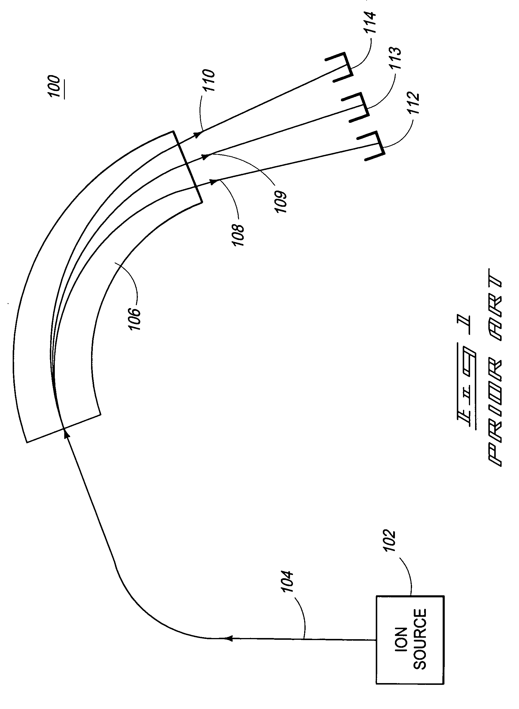
Individual ion beams cannot readily be separated far enough apart to allow use of full sized Faraday cups or discrete dynode pulse counting detectors for each separated beam with existing approaches.

Method used


Image

  • Mass spectrometer and methods of increasing dispersion between ion beams
  • Mass spectrometer and methods of increasing dispersion between ion beams
  • Mass spectrometer and methods of increasing dispersion between ion beams

Examples


Embodiment Construction

[0026]This disclosure of the invention is submitted in furtherance of the constitutional purposes of the U.S. Patent Laws “to promote the progress of science and useful arts” (Article 1, Section 8).

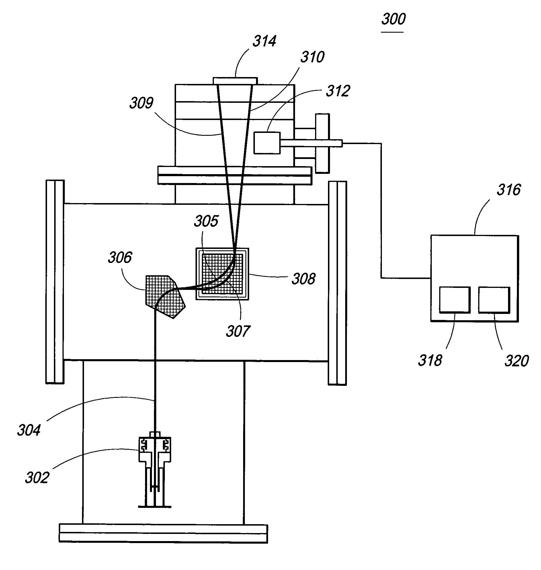
[0027]FIG. 3 shows a wide dispersion mass spectrometer 300 illustrating the main components of a mass spectrometer embodying various aspects of the invention. An ion source 302 generates a beam of ions (e.g., charged particles) 304. The mass spectrometer includes a magnetic sector 306, and an electrostatic sector 308 configured as an EDL. A plurality of ion beams 309, 310 are magnetically separated by the magnetic sector 306. The electrostatic sector 308 receives the plurality of beams from the magnetic sector 306 and the electrostatic sector 308 increases separation between the ion beams. The mass spectrometer also includes a Faraday cup detector 312, and a multichannel plate (MCP) detector having screen 314.

[0028]The ion source 302 is configured to provide stable ion currents. The beams...


PUM


Abstract

A mass spectrometer includes a magnetic sector configured to separate a plurality of ion beams, and an electrostatic sector configured to receive the plurality of ion beams from the magnetic sector and increase separation between the ion beams, the electrostatic sector being used as a dispersive element following magnetic separation of the plurality of ion beams. Other apparatus and methods are provided.

Description

GOVERNMENT RIGHTS[0001]This invention was made with Government support under Contract No. DE-AC07-99ID13727 awarded by the U.S. Department of Energy. The Government has certain rights in the invention.TECHNICAL FIELD[0002]Aspects of the invention generally relate to mass spectrometers and methods of increasing dispersion between ion beams.BACKGROUND OF THE INVENTION[0003]Isotopic analysis of materials provides increased amount of information relative to information generated by traditional chemical analyses. Although qualitative and quantitative structural analyses identify the chemical composition of a compound or individual molecules of the compound, isotopic analysis provides additional information regarding the source, origin and formation of such compounds and molecules.[0004]Mass spectrometers are well known and are used for wide ranging applications, such as isotope ratio monitoring, chemical analysis ranging from environmental analysis (e.g., detection of poisons) to the ana...

Claims


Application Information

Patent Timeline
Patent Type & Authority Patents(United States)
IPC IPC(8): H01J49/48H01J49/32H01J49/02H01J49/10H01J49/42
CPCH01J49/10H01J49/025
Inventor APPELHANS, ANTHONY D.OLSON, JOHN E.DELMORE, JAMES E.
Owner BATTELLE ENERGY ALLIANCE LLC
Learn More