System and method of digital system performance enhancement

a digital system and performance enhancement technology, applied in the field of digital electronic systems, can solve the problems of insufficient duration/period of clock, inability to model, design and verify asynchronous systems, and inability to achieve the performance of such a digital system. half or less than

Inactive Publication Date: 2006-01-10
BOARD OF GOVERNORS FOR HIGHER EDUCATIONS STATE OF RHODE ISLAND & PROVIDENCE PLANTATIONS THE
View PDF11 Cites 40 Cited by
  • Summary
  • Abstract
  • Description
  • Claims
  • Application Information

AI Technical Summary

Benefits of technology

[0012]Briefly, according to an aspect of the present invention, the frequency of a system clock is automatically increased until a system error is detected, then the frequency of the clock is automatically slightly reduced to a value that does not cause system errors.

Problems solved by technology

Modeling, designing and verifying asynchronous systems has in practice been found to be extremely difficult, even with modern asynchronous techniques.
However, an inherent difficulty and performance penalty with synchronous systems is that the duration / period of the clock must be large enough to handle worst-case operating conditions and manufacturing tolerances.
Therefore, the performance of such a digital systems is often half or less than what it would be but for the worst-case.
However, the delays are not constant, but vary with differences in the manufacturing process, variations in the power supply voltage, variations in the operating temperature and humidity, as well as other factors.
Consequently, the average user experiences significantly lower performance than is actually necessary.

Method used


Image

  • System and method of digital system performance enhancement
  • System and method of digital system performance enhancement
  • System and method of digital system performance enhancement

Examples


first embodiment

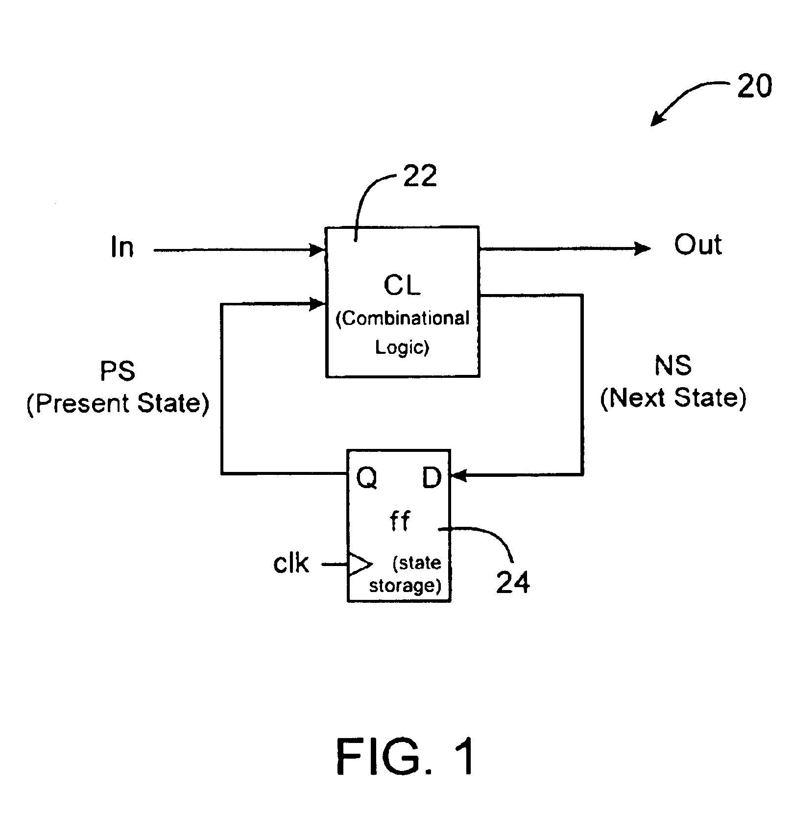
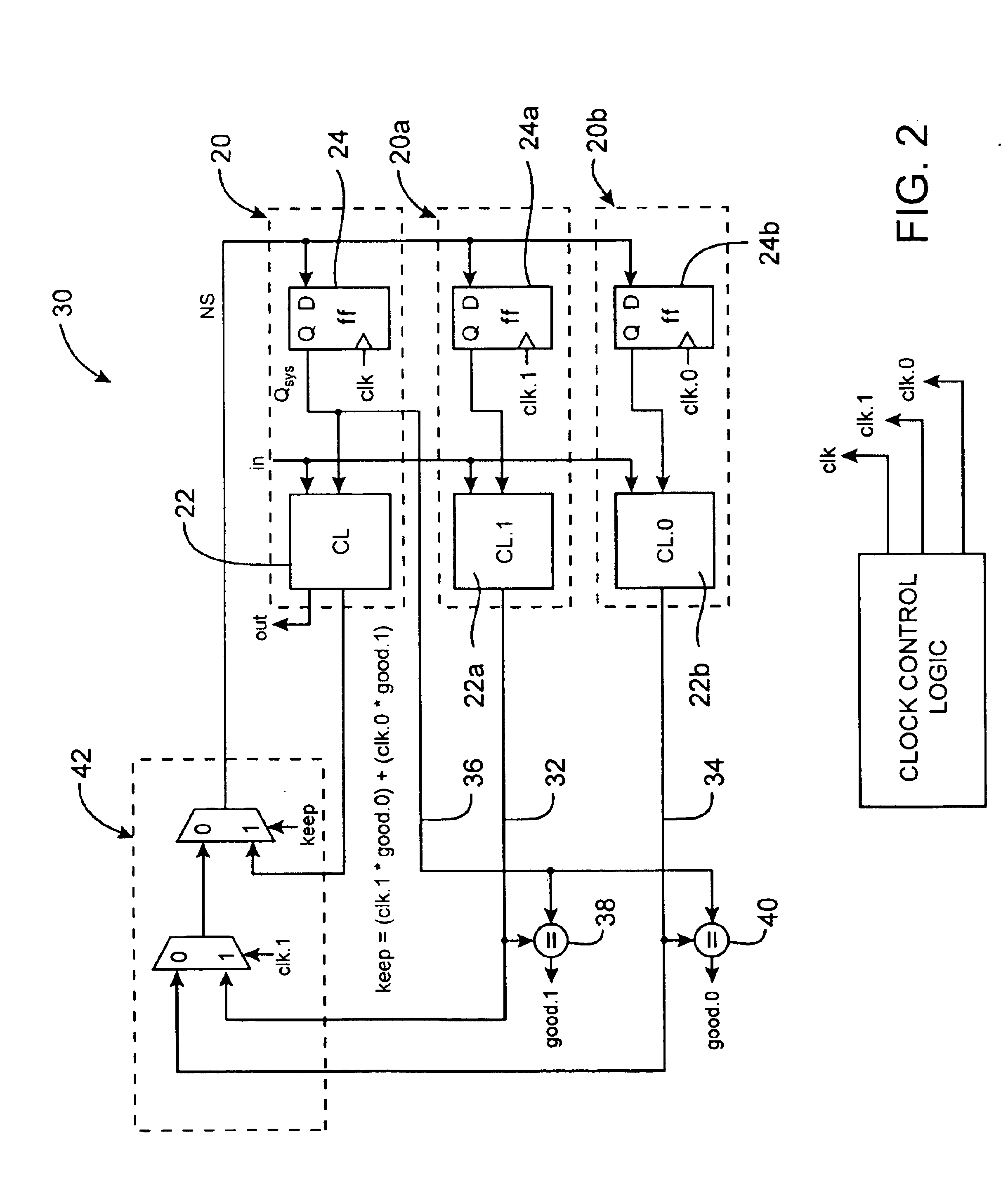
[0030]FIG. 2 illustrates a digital system 30 according to the present invention. The digital system 30 includes two copies 20a, 20b of a main digital synchronous system 20 illustrated in FIG. 1, wherein each of the copies 20a, 20b operates at half the speed of the main digital synchronous system 20. One of the copies replicates the results of the main digital synchronous system 20 in odd cycles, while the other copy replicates the results in even cycles. The two half-speed systems 20a, 20b are operated one main system cycle out-of-sync with each other. Both of the half-speed systems' 20a, 20b outputs on lines 32, 34 respectively are compared with the main system output on the line 36 in alternate cycles using comparators 38, 40. If there is a difference between the two outputs (e.g., between the signals on lines 32 and 36), an error is detected and selection logic 42 selects the output signal from the half-speed system, assuming of course the error was caused by the higher speed sys...

embodiment 70

[0044]FIG. 4 illustrates a first alternative embodiment 70 of the present invention. This embodiment may be realized at the gate and latch level or at the register level. The system illustrated in FIG. 4 has a hardware cost that increases at the same rate as the performance (e.g., about 2× hardware cost for 2× performance increase, while the power also increases by a factor of about two). This solution is also easier to build and does not increase the amount of logic (gate delay) in the critical path. This solution is applied at the functional level in a pipelined system. FIG. 5 illustrates a timing diagram for the first alternative embodiment system 70 illustrated in FIG. 4.

[0045]For the purposes of describing this embodiment, and certainly not by limitation, it is assumed that the system is pipelined. In a pipelined system (common in today's processors), the work of the original combinational logic is divided up into several sections / stages. Each stage does part of the work of the...

embodiment 100

[0055]FIG. 6 illustrates yet another embodiment 100 of the invention. Notably, the embodiment 100 illustrated in FIG. 6 realizes a 2× performance for less than a 2× increase in hardware cost, while power increases by a factor of four. A major feature of this embodiment is its applicability to all digital systems, via the general digital system model illustrated in FIG. 1.

[0056]Referring to FIG. 6, this embodiment is premised on creating a mini-version of a proportional pipe, but constructing the stages' combinational logic in a different manner. Assuming the original combinational logic block CL illustrated in FIG. 2 is split it into two equal-delay combinational logic sections CLa 102 and CLb 104 (i.e., we increase the pipelining by a factor of two). This allows the clock frequency to be doubled, and using a two-phase clocking system the implicit system frequency can be increased by another factor of two. However, since we only get a result every complete pass through the pipeline ...


PUM


Abstract

The present invention performs a digital computation with a lower than worst-case-required clock period (i.e., a faster clock), and at the same time performs the same computation with a larger, worst-case-assumed, clock period (i.e., a slower clock) on a second system with identical hardware. The outputs from the computations are compared to determine if an error has occurred. If there is a difference in the two answers, the faster computation must be in error (i.e., a miscalculation has occurred), and the system uses the answer from the slower system. In one embodiment, the present invention utilizes two copies of the slower system that each run half as fast as the main system. However, the two copies produce results in the aggregate at the same rate as the main system, which is running at a much faster rate than possible without the invention. Hence the present invention improves performance (e.g., speed), albeit with more hardware. Advantageously, the present invention dynamically adapts to achieve the best performance possible under the actual operating conditions.

Description

CROSS REFERENCE TO RELATED APPLICATIONS[0001]This application claims priority to U.S. Patent Application Ser. No. 60 / 429,736, filed Nov. 27, 2002, now superseded and is a continuation-in-part application of U.S. patent application Ser. No. 09 / 672,128, filed on Sep. 27, 2000, now abandoned, which claims priority to U.S. Patent Application Ser. No. 60 / 156,219, filed on Sep. 27, 1999 now superseded. all the aforementioned applications being incorporated by reference in their entireties.GOVERNMENT LICENSE[0002]This invention was made with government support under Grant Nos. MIP-9708183, EIA-9729839, and DUE-9751215, awarded by the National Science Foundation. The government has certain rights in this invention.BACKGROUND OF THE INVENTION[0003]The invention relates to the field of digital electronic systems, and in particular to synchronous digital electronic systems.[0004]Computers, including their central processing units (e.g., Intel Pentium), cell phones, microwave ovens and practica...

Claims


Application Information

Patent Timeline
Patent Type & Authority Patents(United States)
IPC IPC(8): H04L7/00
CPCG01R31/31707G01R31/31725G01R31/3172
Inventor UHT, AUGUSTUS K.
Owner BOARD OF GOVERNORS FOR HIGHER EDUCATIONS STATE OF RHODE ISLAND & PROVIDENCE PLANTATIONS THE
Why Eureka
Try Eureka