Steering controlling device

a controlling device and steering technology, applied in the direction of position/direction control, non-deflectable wheel steering, vehicle position/course/altitude control, etc., can solve the problems of reducing efficiency, deteriorating fuel consumption of vehicles, loss of converters, etc., to suppress the frequency of operation of converters, improve efficiency, and output torque sufficient

Inactive Publication Date: 2006-01-17
MITSUBISHI ELECTRIC CORP
View PDF21 Cites 27 Cited by
  • Summary
  • Abstract
  • Description
  • Claims
  • Application Information

AI Technical Summary

Benefits of technology

[0007]It is an object of the present invention to solve the above-mentioned problems inherent in the conventional technique and to provide a steering controlling device which generates a sufficient output torque of a motor under various steering conditions, suppresses a frequency of operation of a converter, and improves an efficiency, in use of the converter. Another object of the present invention is to enable a fail safe treatment when the converter is disordered.

Problems solved by technology

Therefore, there are serious problems that an efficiency is lowered by a loss in the converter, a fuel consumption of a vehicle is deteriorated by over-discharge of a battery or an increment of generating power, and an effect of an electric power steering system, which is originally aimed to improve the fuel consumption by its high efficiency, is not obtainable.
Further, in the conventional device, failures of the converter are not considered.

Method used


Image

  • Steering controlling device
  • Steering controlling device
  • Steering controlling device

Examples


embodiment 1

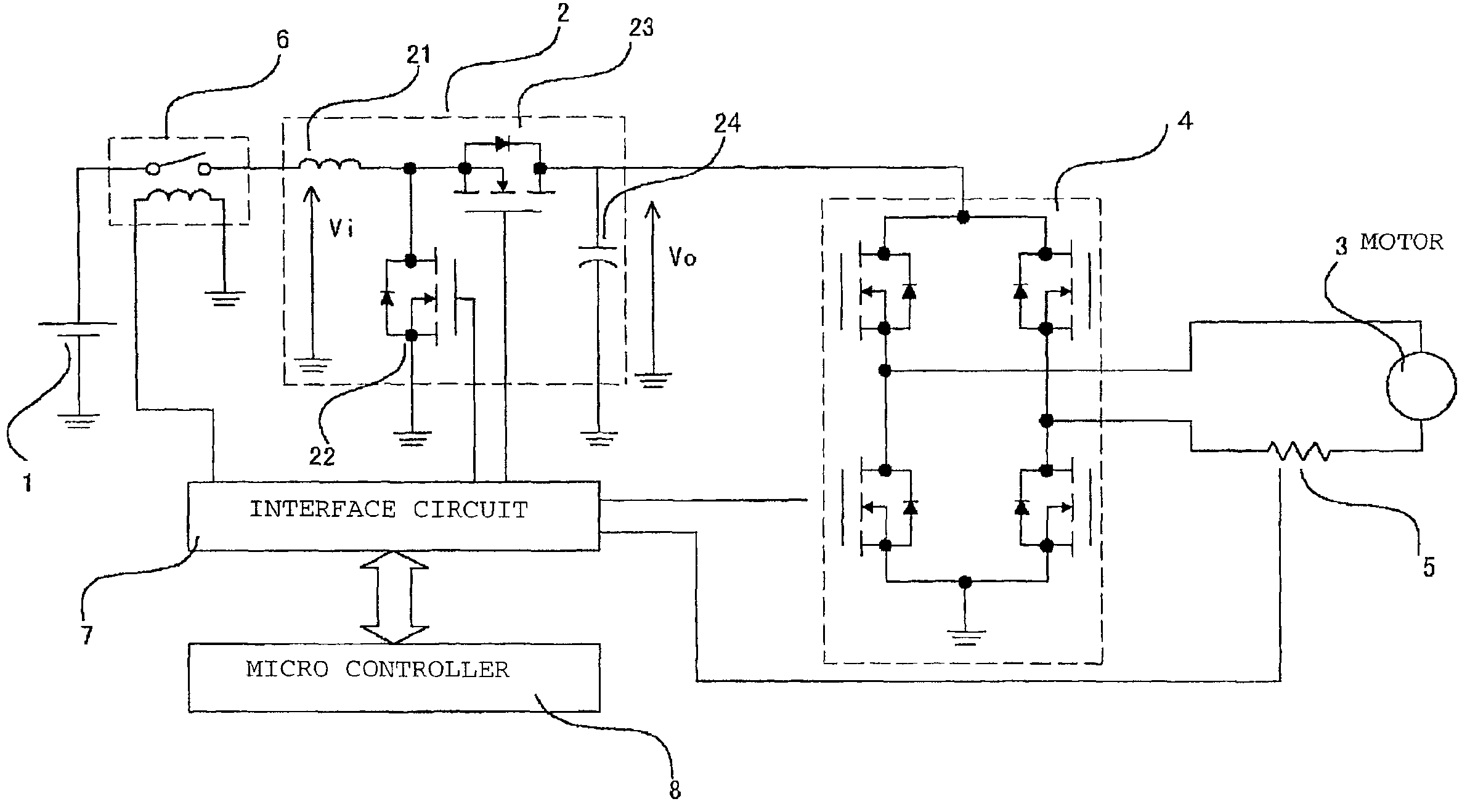
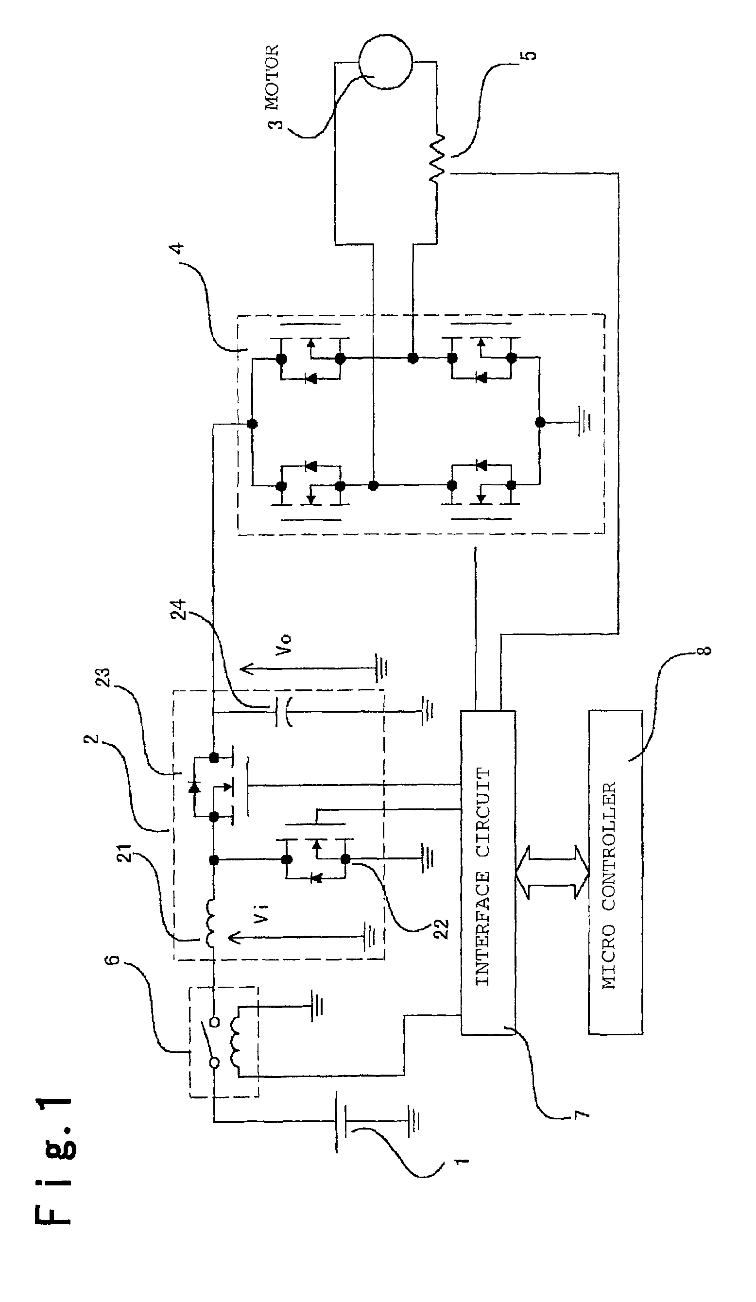
[0035]FIG. 1 illustrates an embodiment of the present invention. Numerical reference 1 designates a battery; and numerical reference 2 designates a first converter for boosting a voltage of the battery 1, the first converter is formed by a choke coil 21, a first switching element 22, a second switching element 23, and a capacitor 24. Numerical reference 3 designates a motor connected to a steering system (not shown), the motor is a d.c. motor using a magnetic field by a permanent magnet. Numerical reference 4 designates a bridge circuit for reversibly driving the motor 3; numerical reference 5 designates a motor current detecting circuit for detecting a current of the motor 3; numerical reference 6 designates a relay for allowing or prohibiting a supply of an electric current to the first converter 2 or the bridge circuit 4; and numerical reference 7 designates an interface circuit for connecting the above-mentioned various circuits to a micro controller 8.

[0036]The motor 3 is appro...

embodiment 2

[0060]Although the first converter 2 is started and stopped based on only the result of the operation of the motor current feedback control in the above embodiment, the output voltage from the first converter may be set to be a predetermined value by a feedback control to obtain a constant voltage. Accordingly, a voltage after boosting is stabilized, controllability of the motor is further improved, and steering feeling is improved in a power steering device.

[0061]Further, the first converter 2 may be driven so that a voltage Vo after boosting is a predetermined value or less. Accordingly, it is possible to protect various circuit, to which the output voltage Vo from the first converter 2 is applied, from a high voltage.

embodiment 3

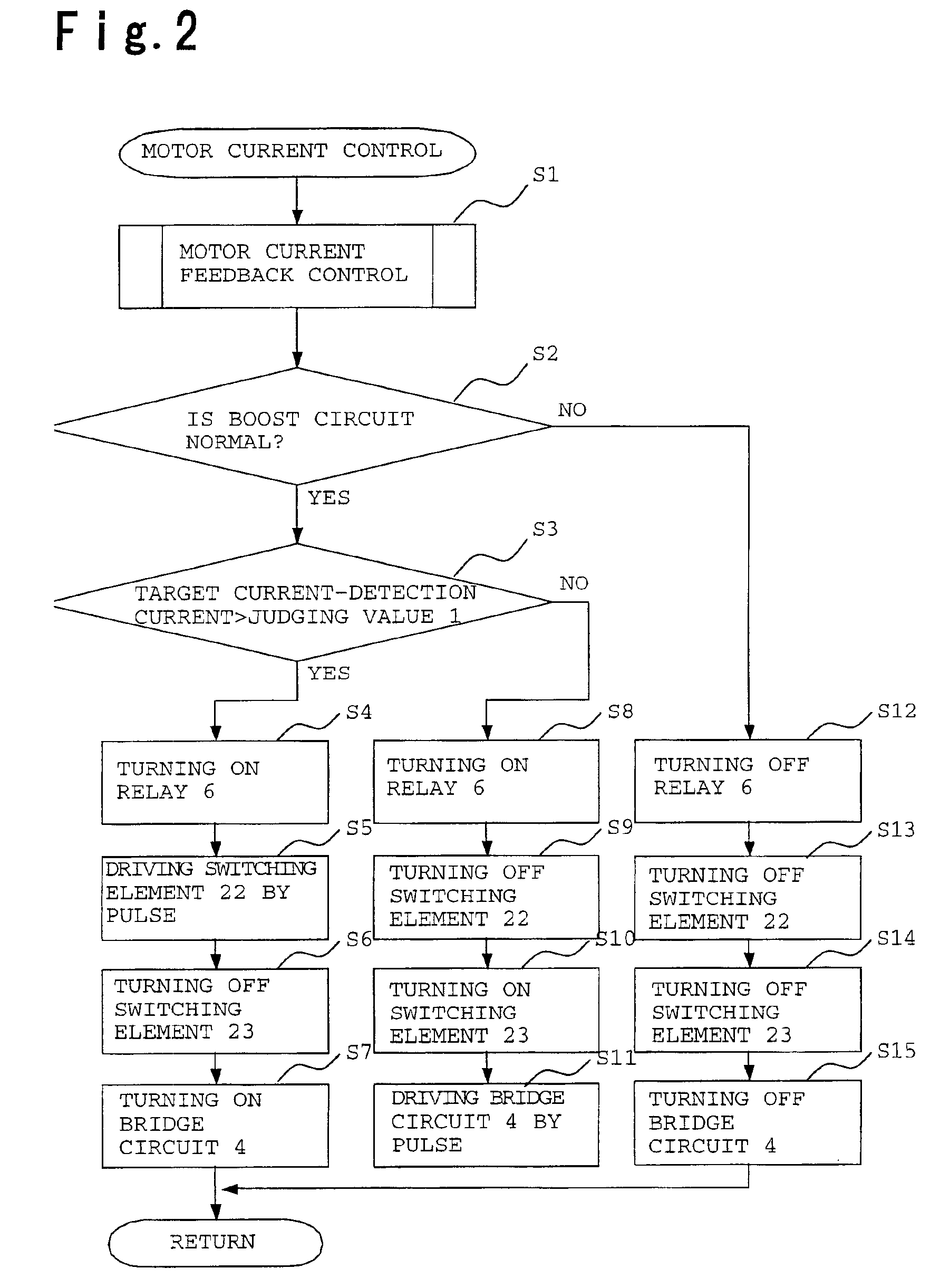
[0062]Although it is judged whether or not the boosting operation is necessary based on the deviation of the electric current in the above embodiment, necessity of a boosting operation may be judged when an impressed voltage to a motor is a predetermined value or more. In other words, the impressed voltage is high in a case that a motor current feedback control indicates a PWM duty of about 100% by an influence of a counter-electromotive force of the motor. In this case, in order to obtain a desirable motor output torque, it is necessary to further increase the impressed voltage. Therefore, when the impressed voltage is the predetermined value or more, the boosting operation is conducted. In this case, a voltage is boosted before a current deviation is generated, whereby steering feeling can be further improved.

[0063]Further, by operating the counter-electromotive force from the impressed voltage and a motor current and judging that a rotational speed is high when the counter-electr...


PUM


Abstract

A steering controlling device comprising a power source, a motor connected to a steering system, a motor driving circuit converting a power source voltage to a predetermined voltage and applying the voltage to the motor, and a controlling means for controlling the motor driving circuit, wherein the controlling means controls the motor driving circuit so as to boost the power source voltage when a rotational speed of the motor is a predetermined value or more, whereby a sufficient motor output torque is obtainable under various steering conditions in use of a converter, an efficiency is improved by suppressing a frequency of operating the converter, and an appropriate fail safe treatment is conducted when the converter is disordered.

Description

BACKGROUND OF THE INVENTION[0001]1. Field of the Invention[0002]The present invention relates to a steering controlling device for automobiles and so on.[0003]2. Discussion of Background[0004]In a conventional technique, an electric power steering device disclosed in Japanese Unexamined Patent Publication JP-A-7-76280 is known, wherein enhancement of an efficiency of power conversion is aimed. FIG. 5 is a block chart illustrating a structure of a conventional device. In the conventional electric power steering device, when a vehicle speed is low, it is judged that a load of a motor is high, whereby a voltage of power source is boosted, and the motor is driven by the boosted voltage.[0005]However, since the conventional device is constructed as described above, the power source is boosted when a vehicle speed is low, whereby a frequency of using the converter is increased. Therefore, there are serious problems that an efficiency is lowered by a loss in the converter, a fuel consumpti...

Claims


Application Information

Patent Timeline
Patent Type & Authority Patents(United States)
IPC IPC(8): H02P7/00B62D6/00B62D5/04B62D101/00B62D117/00B62D119/00B62D137/00H02P29/00
CPCB62D5/0463B62D5/046
Inventor KIFUKU, TAKAYUKI
Owner MITSUBISHI ELECTRIC CORP
Why Eureka
Try Eureka