Digital delay locked loop and control method thereof

Active Publication Date: 2006-01-17
SK HYNIX INC
View PDF12 Cites 33 Cited by
  • Summary
  • Abstract
  • Description
  • Claims
  • Application Information

AI Technical Summary

Benefits of technology

[0056]It is, therefore, a primary object of the present invention to provide a digital delay locked loop and a method for con

Problems solved by technology

The reason why the DLL is used in the SDRAM is that a phase is delayed while the external clock passes through an input clock buffer, a line loading, a data output buffer and other logic circuits, such that the phases of the external clock and the internal clock are mismatched.
Under a situation that noise is not considered in the DLL, a state error (i.e., skew) exists as much as a resolution of the unit dela

Method used


Image

  • Digital delay locked loop and control method thereof
  • Digital delay locked loop and control method thereof
  • Digital delay locked loop and control method thereof

Examples


Embodiment Construction

[0076]Hereinafter, the preferred embodiments of the present invention will be described in detail with reference to the accompanying drawings.

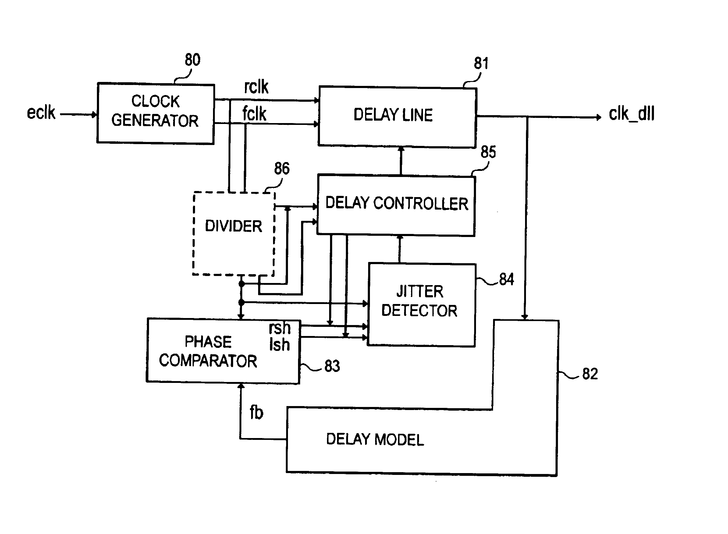
[0077]FIG. 8 is a block diagram of a digital DLL in accordance with an embodiment of the present invention.

[0078]Referring to FIG. 8, the DLL of the present invention includes: a clock generator 80 for receiving an external clock eclk to generate source clocks rclk and fclk and a reference clock ref; a delay line 81 provided with a plurality of unit delay for delaying the source clocks rclk and fclk for a predetermined time; a delay model 82 for reflecting a delay time of an actual internal circuit to an output clk_dll of the delay line 81; a phase comparator 83 for comparing the reference clock ref with a feedback clock fb outputted from the delay model 82; a jitter detector 84 for detecting a maximum jitter time point and generating a multi-delay enable signal en in response to phase comparison signals lsh and rsh; and a delay controller 85 ...


PUM


Abstract

There is provided a digital delay locked loop (DLL) which is capable of minimizing a jitter by predicting and detecting a maximum jitter timing. The digital delay locked loop includes: a clock generator for generating a source clock and a reference clock; a delay line provided with a plurality of unit delays, for delaying the source clock by a predetermined time; a delay model for reflecting a delay time of an actual internal circuit to an output of the delay line; a phase comparator for comparing a phase of the reference clock with a phase of a feedback clock outputted from the delay model; a jitter detector for detecting a maximum jitter timing in response to a phase comparison signal outputted from the phase comparator and generating a multi-delay enable signal; and a delay controller for controlling a delay amount of the delay line by unit-delay unit or multi-delay unit in response to the phase comparison signal and the multi-delay enable signal.

Description

FIELD OF THE INVENTION[0001]The present invention relates to a delay locked loop (DLL) for use in a semiconductor memory device, such as a double data rate (DDR) synchronous dynamic random access memory (SDRAM) or a single data rate (SDR) SDRAM; and, more particularly, to a DLL having an improvement in a jitter characteristic.DESCRIPTION OF THE PRIOR ART[0002]A delay locked loop (DLL) is a circuit that controls a timing of data, which is outputted out of a semiconductor memory device (e.g., an SDRAM) based on an external clock. Here, the external clock is a clock that is inputted from an outside of the semiconductor memory device. In order to transfer data to a chipset without any error, a clock of the SDRAM should be synchronized with that of the chipset.[0003]The reason why the DLL is used in the SDRAM is that a phase is delayed while the external clock passes through an input clock buffer, a line loading, a data output buffer and other logic circuits, such that the phases of the ...

Claims


Application Information

Patent Timeline
IPC IPC(8): H03L7/06G11C11/407G11C11/4076H03L7/081H03L7/089
CPCH03L7/089H03L7/0814H03L7/0816G11C11/407
Inventor KIM, KYUNG-HOON
Owner SK HYNIX INC
Why Eureka
Try Eureka