Microvalve normally in a closed position

a micro-valve and closed position technology, applied in the field of components, can solve the problems of piezoceramic depolarization and carry out active movement in the direction of the membrane, and achieve the effect of increasing the range of application of the valve and increasing the throughput ra

Inactive Publication Date: 2006-01-31
FRAUNHOFER GESELLSCHAFT ZUR FOERDERUNG DER ANGEWANDTEN FORSCHUNG EV
View PDF13 Cites 60 Cited by
  • Summary
  • Abstract
  • Description
  • Claims
  • Application Information

AI Technical Summary

Benefits of technology

[0021]A further advantage of the present invention is that, due to the fact that the circumference of the valve shutter is freely selectable and can be designed to be large, higher throughput rates may be achieved than with conventional valves, in which merely one small opening is pressed shut by an active element.
[0022]Due to the provision of a membrane for separating the actor from the fluid to be switched, the inventive valve is suitable, as opposed to valves which, for example, use electrostatic attraction as the switching force, both for liquids and gases or mixtures of same, whereby the range of application of the valve is increased.
[0023]In accordance with one embodiment the inventiv

Problems solved by technology

Even though the bending converter described with reference to FIGS. 7a to 7c is fast, exhibits low energy consumption, large/high stroke and a strong force, and, in addition, has the advantage, in particular with regard to employment in microfluidics, that it causes the medium to be switched to be separated from the piezoceramic, a drawback of this type of bending converter is that it can only carry out an active movement in the direction of the membrane (downward in FIGS. 7a to 7c) due to the unsymmetrical nature of the piezoeffect as has been described with r

Method used


Image

  • Microvalve normally in a closed position
  • Microvalve normally in a closed position
  • Microvalve normally in a closed position

Examples


Embodiment Construction

[0035]Before various embodiments of the present invention will be described with reference to the figures, it shall be pointed out that like elements in the various figures have been provided with like reference numerals and that a repeated explanation of identical elements will be omitted in the description of the figures so as to avoid repetitions in the description.

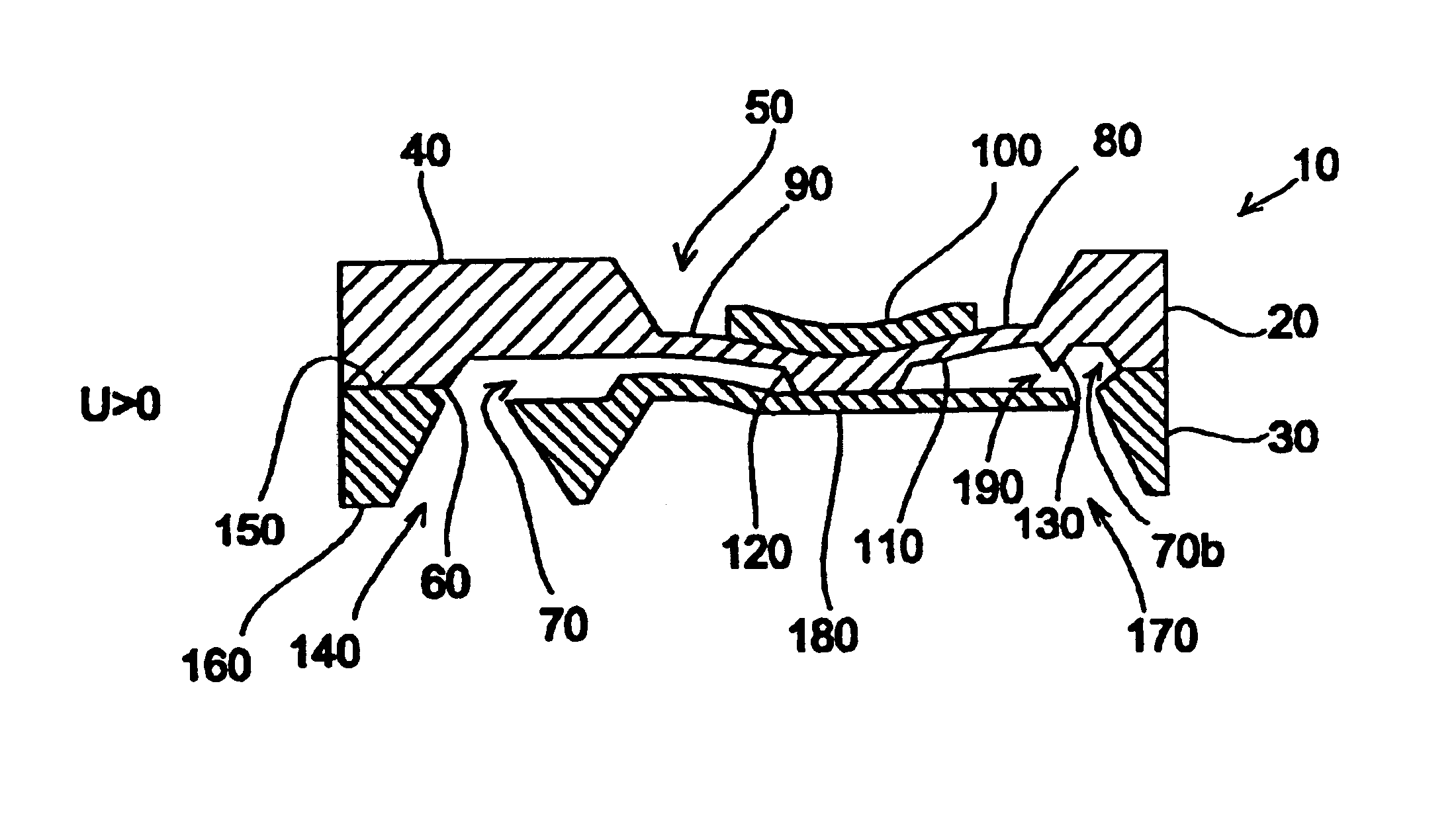
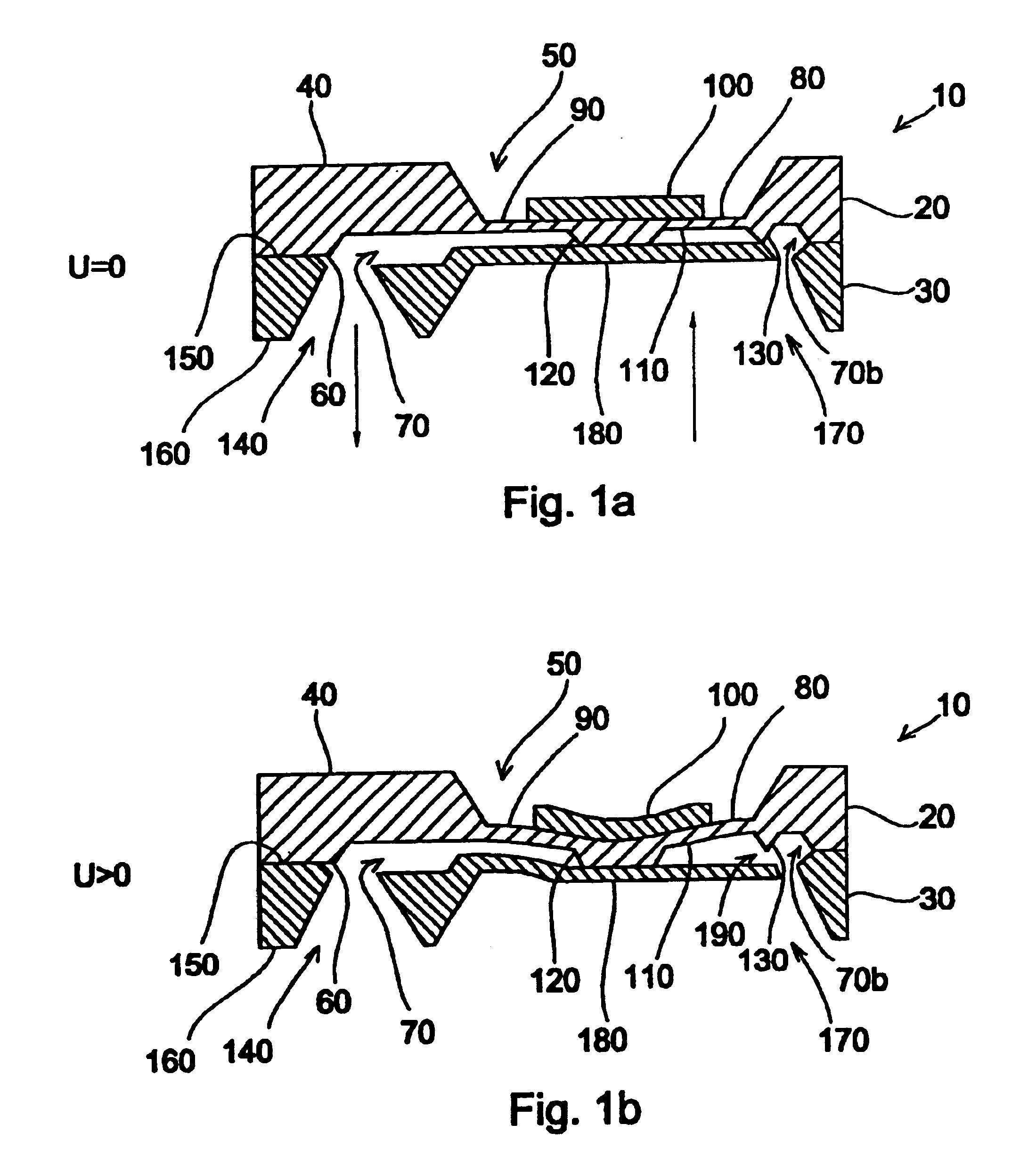
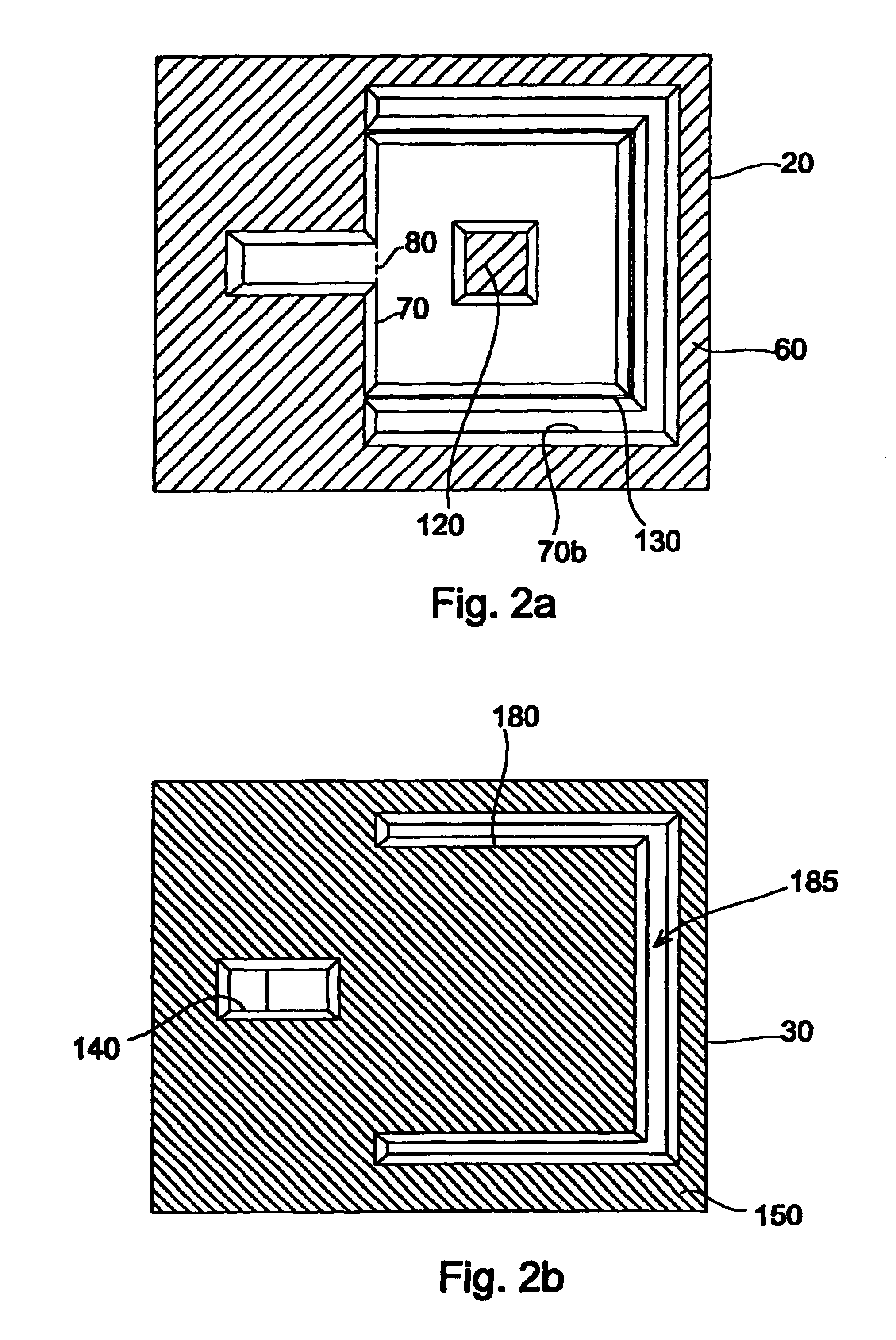
[0036]With reference to FIGS. 1a, 1b, 2a and 2b, an embodiment of an NC valve in accordance with the present invention will initially be described, wherein FIGS. 1a and 1b show side sectional views of the valve in a normally closed state and an open state, respectively, of the valve, and FIGS. 2a and 2b show a bottom view of an actor chip and a top view of a flap chip, respectively, of the valve in the normally closed state of the valve. It shall be pointed out that FIGS. 1a, 1b, 2a and 2b show the structures, by way of example, with slopes such as occur in KOH etching, it being possible, however, to produce the struct...


PUM


Abstract

A microvalve with a normally closed state includes a membrane, an actuation means for controllable deformation of the membrane as well as a valve shutter deformable by the controllable deformation of the membrane. The valve shutter at least partially opposes the membrane and rests, in a first position in the normally closed state of the valve, along a sealing lip arranged between the valve shutter and the membrane. The sealing lip is arranged such that an outlet of the valve, which outlet is in fluid communication with an interrupted section of the sealing lip, is sealed against an input channel bordering on the valve shutter. In addition, the valve shutter is moldable into a second position so as to bring the outlet into fluidic communication with the input channel in an open state of the valve.

Description

BACKGROUND OF THE INVENTION[0001]1. Field of the Invention[0002]The present invention relates to components which are micromechanically structured, and in particular to microvalves as are used, for example, in medical engineering or in pneumatics, and to micropumps using such microvalves.[0003]2. Description of Prior Art[0004]The growing demand for miniaturized and integrated systems has recently led to the development of micromechanic structural parts, such as microvalves and micropumps. In order to effect the necessary mechanical actuation of such components, frequent use is made of piezoceramics which contract in the direction of polarization of the piezoceramic upon application of voltage.[0005]To illustrate the operation of such piezoceramics, FIGS. 6a, 6b and 6c show the state of a piezoceramic in three different voltage drive states. The piezoceramic 900, shown in FIGS. 6a to 6c, has metallizations 910a and 910b on two opposing outer surfaces of piezoceramic 900. Metallizatio...

Claims


Application Information

Patent Timeline
IPC IPC(8): F15C5/00F16K99/00
CPCF15C5/00F16K99/0001F16K99/0007F16K99/0015F16K99/0048F16K2099/0094F16K2099/0074F16K2099/0086F16K99/0034
Inventor RICHTER, MARTIN
Owner FRAUNHOFER GESELLSCHAFT ZUR FOERDERUNG DER ANGEWANDTEN FORSCHUNG EV
Why Eureka
Try Eureka