Brushless direct-current motor of radial core type having a structure of double rotors and method for making the same

a brushless, direct-current technology, applied in the direction of stator/rotor body manufacturing, magnetic circuit rotating parts, magnetic circuit shape/form/construction, etc., can solve the problems of loss of yoke material, complicated yoke structure, and special-purpose expensive dedicated winding machine use, so as to improve the productivity of coil windings and motor output.

Inactive Publication Date: 2006-01-31
AMOTECH
View PDF2 Cites 87 Cited by
  • Summary
  • Abstract
  • Description
  • Claims
  • Application Information

AI Technical Summary

Benefits of technology

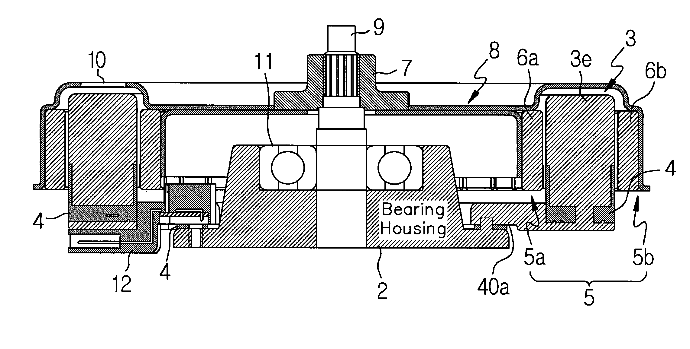
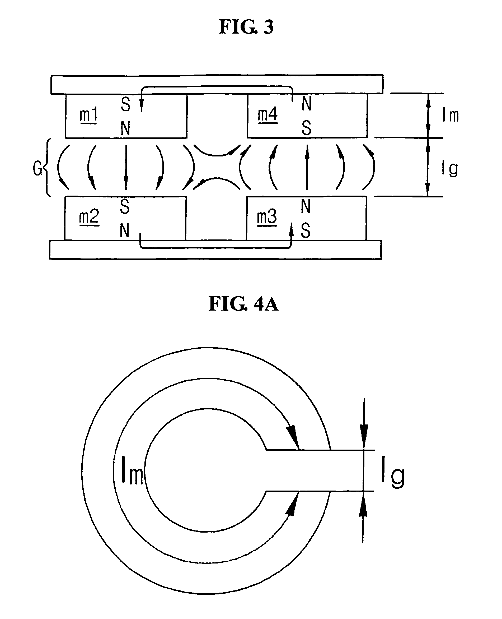
[0023]To solve the above problems, it is an object of the present invention to provide a brushless direct-current (BLDC) motor having a radial core type double rotor structure in which permanent magnet rotors are disposed in the inner and outer sides of a stator core, respectively, to thus form a magnetic circuit by the inner and outer permanent magnets and rotor yokes and to thereby enable a complete division of a stator core and thus greatly enhance productivity of coil windings and a motor output.
[0024]It is another object of the present invention to provide a brushless direct-current (BLDC) motor having a radial core type double rotor structure which can make the most of merits of an axial double rotor type and a radial core type and improve demerits thereof.
[0025]It is still another object of the present invention to provide a brushless direct-current (BLDC) motor having a radial core type double rotor structure which can greatly enhance productivity of assembling a stator by a stator structure capable of wiring coils by automatically positioning and fixing a plurality of stator core assemblies to a core support plate when employing a double rotor and division type stator core structure.

Problems solved by technology

However, such a yoke structure causes loss of a yoke material when fabricating a stator.
In addition, a special-purpose expensive dedicated winding machine must be used for winding coils around the yoke during mass-production, because the yoke structure is complicated.
Also, since a mold for fabricating a stator is expensive, initial investment costs become high.
However, since a portion occupied by armature windings includes an air gap, a magnetic resistance is high and thus a magnetic flux density is low in comparison with the number of magnets.
Thus, the axial coreless type motor should use higher performance magnets and the more number of magnets, in comparison with a radial core type motor of an equivalent output, and finally may raise production cost.
However, although the axial coreless gap type motor has the above-described various kinds of advantages, it is in a more disadvantageous position than a radial type motor, in view of axial vibration.
Accordingly, there have been a number of proposals in order to solve the problems that the initial investment cost becomes very high, and productivity of winding coils around the stator core is low.
Thus, the existing problems of the low coil winding workability, the high material loss, the high investment cost for the winding machine, etc., still remain, and the coil windings should be provided doubly at the inner / outer sides of the stator core.
Also, a winding machine for winding coils at the inner side of the core and that for winding coils at the outer side of the core cannot be commonly used.
As a result, the investment cost for winding machines increases as much as an increase in the motor output.

Method used


Image

  • Brushless direct-current motor of radial core type having a structure of double rotors and method for making the same
  • Brushless direct-current motor of radial core type having a structure of double rotors and method for making the same
  • Brushless direct-current motor of radial core type having a structure of double rotors and method for making the same

Examples


first embodiment

[0137]FIG. 10A is a perspective view of a perfect division type stator core which is used in the present invention. FIG. 10B is a cross-sectional view cut along line A—A of FIG. 10A. FIG. 11A is an exploded perspective view showing a relationship of coupling a stator core assembly and a core support plate according to the present invention. FIG. 11B is a partially enlarged perspective view of a core support plate. FIG. 11C is an enlarged view showing a coupling state of the core support plate.

[0138]As shown in FIGS. 10A and 10B, a division type stator core 3a is formed of a substantially I-shaped form. As shown, coupling grooves 31a and 31b whose sectional areas are of shapes of a semi-circle are vertically formed at opposing positions on both side surfaces. A bobbin 30 made of an insulation material such as a plastic material is combined on the outer circumferences of the side surfaces. A hollow vessel is formed in the middle portion of the bobbin 30, and flanges 30a and 30b are ex...

second embodiment

[0165]FIGS. 13A through 13D are views showing the present invention, in which FIG. 13A is an exploded perspective view showing a relationship of coupling a stator core assembly and a core support plate, FIG. 13B is an enlarged perspective view of the core support plate, FIG. 13C is an enlarged view showing a coupling state of the core support plate, and FIG. 13D is a cross-sectional view cut along line A—A of the division type stator core of FIG. 13A.

[0166]Referring to FIGS. 13A to 13D, a stator according to a second embodiment of the present invention is shown. Here, a cross-sectional structure of a division type stator core 3a′ differs from that of the first embodiment. That is, the vertically formed coupling grooves are not formed in both lateral surfaces of the core 3a′, but a number of first and second coupling protrusions 44′ and 45′ for automatically positioning and supporting a number of stator core assemblies 3c′ to an annular core support plate 4′ are vertically extended d...

third embodiment

[0171]FIG. 14A is an exploded perspective view showing a relationship of coupling a stator core assembly and a core support plate according to the present invention. FIG. 14B is an enlarged view showing a division type stator core.

[0172]Referring to FIGS. 14A and 14B, in the case of a stator according to a third embodiment of the present invention, a structure of a number of stator core assemblies 3c″ is similar to that of the second embodiment. However, coupling protrusions 30c and 30d whose cross-sections are circular or rectangular are extended in the inner portion of the bobbin and the lower portions of the outer flanges 30c and 30b, guide grooves 30e–30h for wiring and guiding coils 3b (not shown) are formed, and coupling holes 47c and 47d corresponding to coupling protrusions 30c and 30d are perforated on the bottom of an annular plate 40 instead of a number of first and second coupling protrusions 44′ and 45′ so that a number of stator core assemblies 3c″ are automatically po...


PUM

PropertyMeasurementUnit
polaritiesaaaaaaaaaa
circumferenceaaaaaaaaaa
conductiveaaaaaaaaaa

Abstract

A radial core type double rotor brushless direct-current motor is provided in which a double rotor structure is employed with inner and outer rotors which are doubly disposed and thus a stator core is completely divided. The motor includes a rotational shaft which is rotatably mounted on a housing of an apparatus, cylindrical inner and outer yokes which are rotatably mounted on the center of the housing, inner and outer rotors including a number of magnets which are mounted with the opposing polarities on the outer surface of the inner yoke and the inner surface of the outer yoke, and a number of cores assemblies which are installed between the inner and outer rotors in which a number of coils are wound around a number of division type cores, respectively.

Description

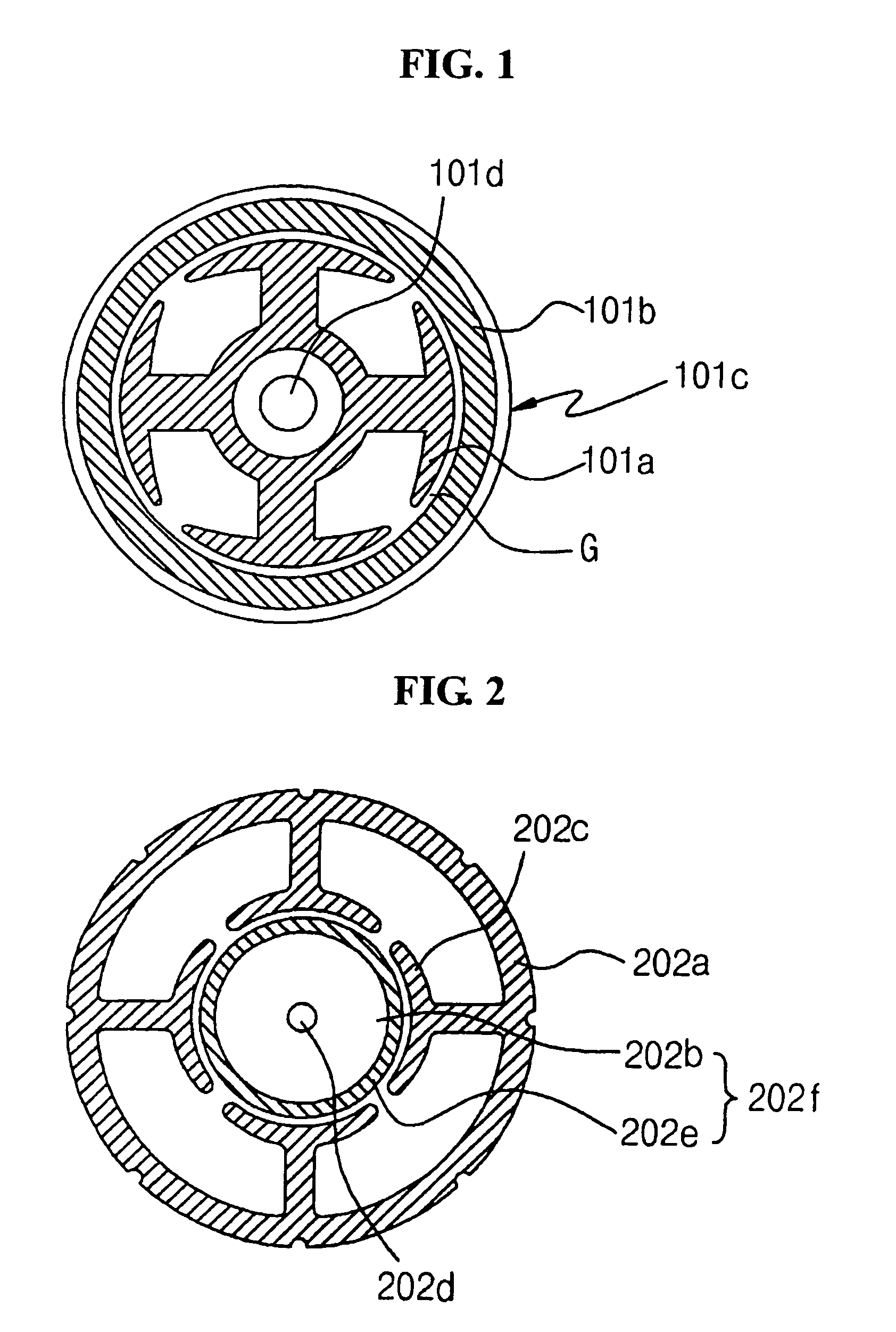
TECHNICAL FIELD[0001]The present invention relates to a radial core type brushless direct-current (BLDC) motor, and more particularly, to a brushless direct-current (BLDC) motor having a radial core type double rotor structure in which double rotors are disposed in the inner and outer sides of a stator, respectively in a radial core type motor, to thereby enable a complete division of a stator core and thus enhance productivity of coil windings and a motor output.BACKGROUND ART[0002]A BLDC motor can be classified into a core type (or radial type) and a coreless type (or axial type), each having a generally cup-shaped (cylindrical) structure, according to whether or not a stator core exists.[0003]A BLDC motor of a core type structure is classified into an internal magnet type of FIG. 2 including a cylindrical stator where coils are wound on a number of protrusions formed on the inner circumferential portion thereof in order to form an electronic magnet structure, and a rotor formed o...

Claims


Application Information

Patent Timeline
Patent Type & Authority Patents(United States)
IPC IPC(8): H02K1/22H02K1/00H02K29/00D06F37/30H02K1/14H02K1/18H02K1/27H02K1/30H02K3/52H02K5/173H02K9/06H02K15/03H02K16/00H02K16/02H02K21/12H02K21/16H02K21/22H02K29/08
CPCD06F37/304H02K1/18H02K1/27H02K1/278H02K1/2786H02K1/30H02K3/522H02K3/524H02K5/1735H02K9/06H02K15/03H02K16/02H02K21/16H02K21/225H02K29/08H02K1/148Y10T29/49011H02K2203/03Y10T29/49009Y10T29/49012H02K1/2791
Inventor KIM, PYUNG KYUJEONG, KYU HYUKSONG, HYUNG GEUNLEE, SANG HAN
Owner AMOTECH
Why Eureka
Try Eureka