Multi-beam scanning apparatus

Inactive Publication Date: 2006-01-31
CANON KK
View PDF12 Cites 8 Cited by
  • Summary
  • Abstract
  • Description
  • Claims
  • Application Information

AI Technical Summary

Benefits of technology

[0036]Trouble such as a shift of the rotational angle of the multi-beam light source unit due to free running

Problems solved by technology

In the prior art, however, when the multi-beam light source unit is to be fixed to the optical box, the whole multi-beam light source unit is rotated through the predetermined angle θ together with the laser driving circuit board, thereby obtaining the line interval T. To realize this, a space enough to rotate the

Method used


Image

  • Multi-beam scanning apparatus
  • Multi-beam scanning apparatus
  • Multi-beam scanning apparatus

Examples


first embodiment

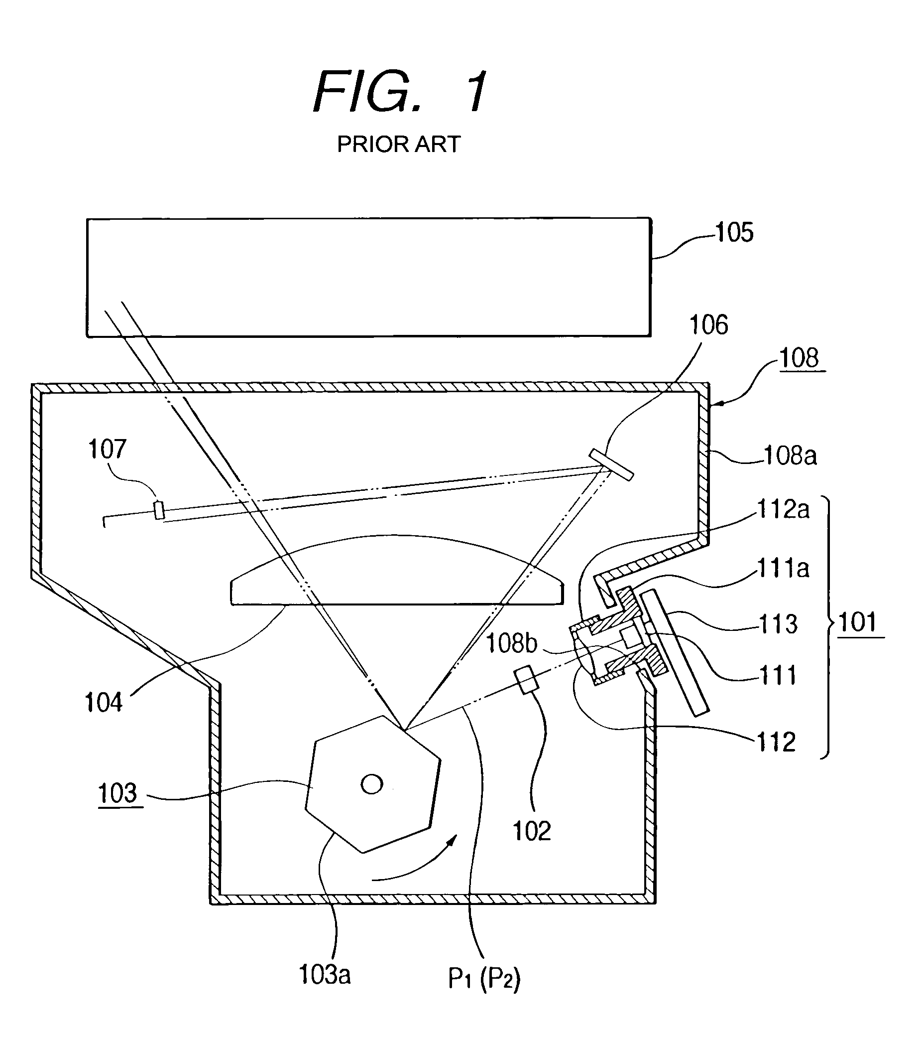
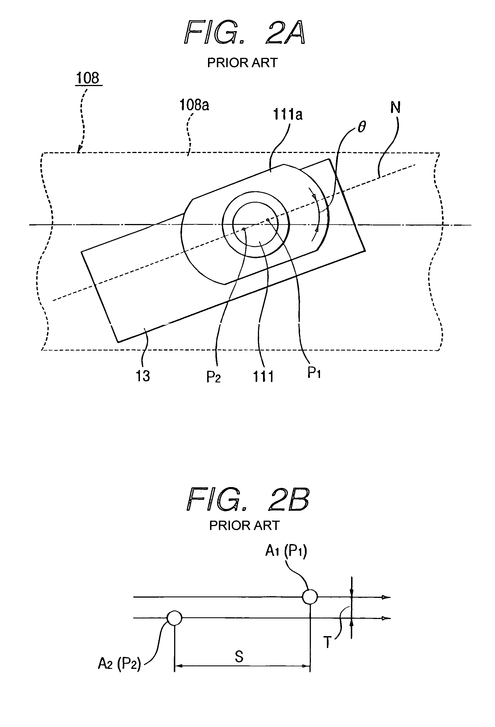
[0061]The line interval T on the rotary drum must be adjusted with submicron-order precision. In the first embodiment, when the multi-beam semiconductor laser is mounted in the laser holder, the laser array N is roughly adjusted to or near to the predetermined inclination angle θ. When the laser holder is mounted in the optical box together with the laser driving circuit board, the angle is finally slightly adjusted to correct an assembly error and the like. Therefore, the final line interval adjustment precision is very high, and the adjustment time can be greatly shortened compared to the conventional wide-range angular adjustment on the optical box. In addition, the large-area laser driving circuit board need not be rotated outside the optical box, and the apparatus can be downsized.

[0062]As a result, this embodiment can realize a small-size, high-precision multi-beam scanning apparatus with low assembly cost.

[0063]Note that this embodiment uses the laser chip with two emission p...

second embodiment

[0064]FIG. 8 shows the multi-beam light source unit. This multi-beam light source unit uses a disk-like laser holder 31a instead of the rectangular laser holder 11a having a reference surface V as an end face. In this case, a reference surface U with a rotational angle θ in mounting a multi-beam semiconductor laser 31 in the laser holder 31a is defined at a notched portion 31b at the circumferential portion of the laser holder 31a.

[0065]As shown in FIG. 9, a laser driving circuit board 33 is mounted on the laser holder 31a such that an upper end face 33a serves as an attachment reference for an optical box (not shown).

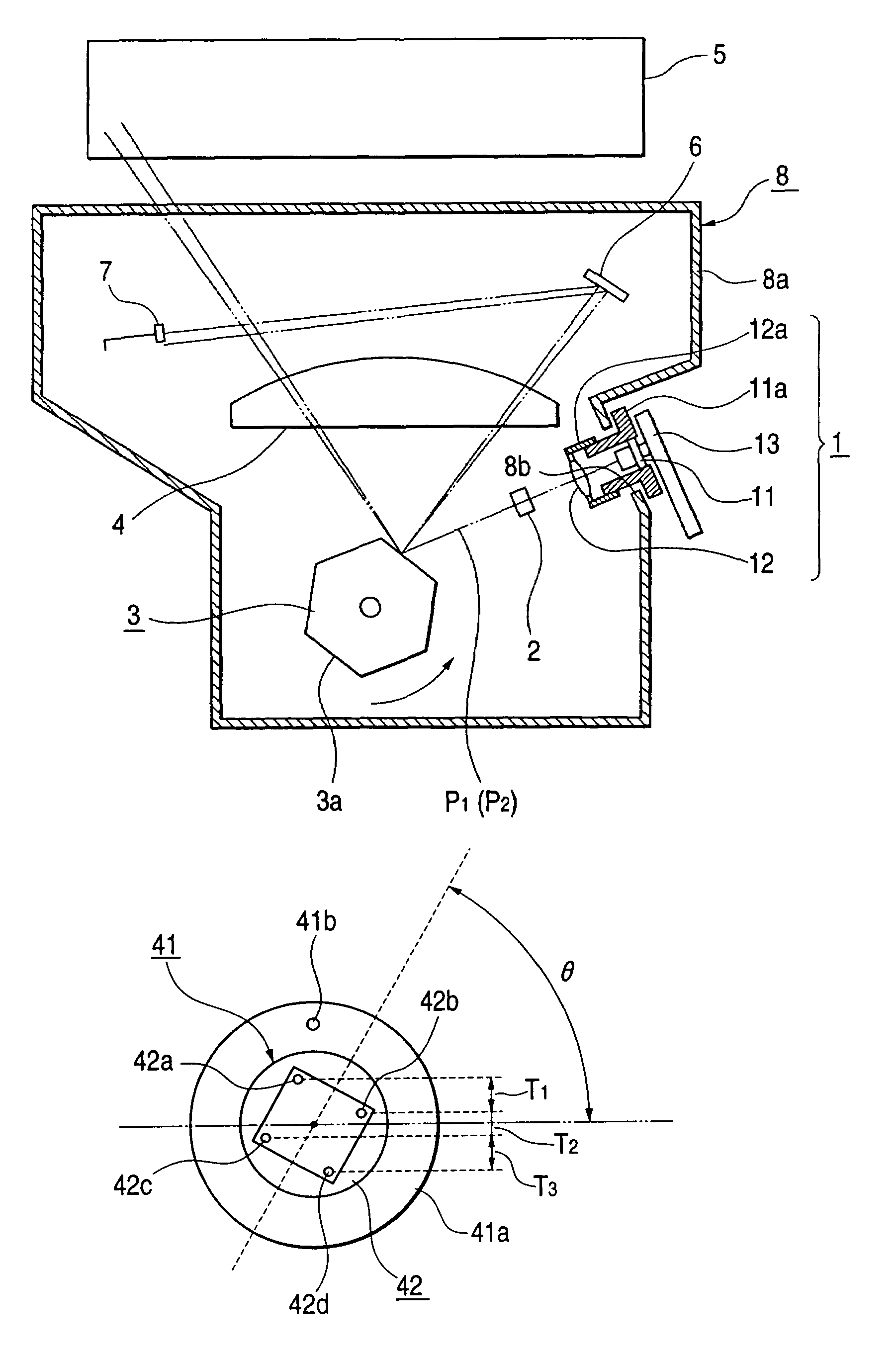
[0066]The edge-emission-type multi-beam semiconductor lasers 11 and 31 on each of which a plurality of emission points are aligned may be replaced with a multi-beam semiconductor laser 41 having a surface-emission-type laser chip 42 on which a plurality of emission points 42a to 42d are two-dimensionally arrayed, as shown in FIG. 10. This multi-beam semiconductor lase...

fourth embodiment

[0081]The fourth embodiment adopts the screws as fixing means, but may adopt an adhesion means with an ultraviolet-curing adhesive or the like. The number of emission points is not limited and may be arbitrarily set to two or more.

[0082]The collimator lens is adhered to the lens barrel preferably with the ultraviolet-curing adhesive, but may be adhered with another adhesive.

[0083]According to the fourth embodiment, the multi-beam light source unit is fastened to the sidewall of the optical box with screws at three or more fixing portions. The center of rotation of the multi-beam light source unit and the emission points of respective laser beams locate on straight lines connecting the fixing portions or within the planar region defined by straight lines connecting all the fixing portions. Thus, the multi-beam light source unit can be stably, firmly mounted in the optical box.

[0084]The fourth embodiment can realize a low-cost, high-performance multi-beam scanning apparatus capable of...


PUM


Abstract

A multi-beam scanning apparatus has a multi-beam semiconductor laser which emits a plurality of laser beams, a laser holder holding the multi-beam semiconductor laser, a multi-beam light source unit having the multi-beam semiconductor laser and the laser holder, scanning imaging unit for scanning a plurality of laser beams emitted by the multi-beam semiconductor laser to form an image on a surface to be scanned, and a housing supporting the scanning imaging unit and the multi-beam light source unit. The multi-beam semiconductor laser is fixed to the laser holder with an inclination at or near a predetermined rotational angle for adjusting a beam interval between the plurality of laser beams.

Description

BACKGROUND OF THE INVENTION[0001]1. Field of the Invention[0002]The present invention relates to a multi-beam scanning apparatus used for a laser beam printer, digital copying machine, and the like.[0003]2. Related Background Art[0004]In recent years, multi-beam scanning apparatuses for simultaneously writing a plurality of lines using a plurality of laser beams are being developed in electrophotographic apparatuses such as a laser beam printer.[0005]The multi-beam scanning apparatus simultaneously scans a plurality of laser beams apart from each other. As shown in FIG. 1, in the multi-beam scanning apparatus, a multi-beam semiconductor laser 111 serving as a light source for a multi-beam light source unit 101 emits two laser beams P1 and P2. The laser beams P1 and P2 are collimated by a collimator lens 112, irradiate a reflecting surface 103a of a rotary polygon mirror 103 via a cylindrical lens 102, and form an image on a photosensitive member on a rotary drum 105 via an imaging l...

Claims


Application Information

Patent Timeline
IPC IPC(8): B41J2/45B41J2/435B41J2/47
CPCB41J2/473B41J2/435
Inventor MOGI, SHINNARUGE, YASUTAKA
Owner CANON KK
Why Eureka
Try Eureka