Flexible printed circuit board unit contributing to reliable soldering and suppression of increased temperature

a printed circuit board unit and flexible technology, applied in the field of flexible printed circuit board units, can solve the problem of limited thermal component location, and achieve the effect of reliably avoiding inflection

Inactive Publication Date: 2006-01-31
FUJITSU LTD
View PDF5 Cites 29 Cited by
  • Summary
  • Abstract
  • Description
  • Claims
  • Application Information

AI Technical Summary

Benefits of technology

[0017]The recording disk drive of this type allows the flexible printed circuit board to extend flat along a plane even when the thermally-conductive material is interposed between the thermally-conductive plate and the flexible printed circuit board on the actuator block. Inflection can reliably be avoided in the flexible printed circuit board. Any undesirable limitation can be avoided when one locates electronic components such as a preamplifier IC and the like as well a

Problems solved by technology

If an inflection is formed in the electrically-isolator

Method used


Image

  • Flexible printed circuit board unit contributing to reliable soldering and suppression of increased temperature
  • Flexible printed circuit board unit contributing to reliable soldering and suppression of increased temperature
  • Flexible printed circuit board unit contributing to reliable soldering and suppression of increased temperature

Examples


first embodiment

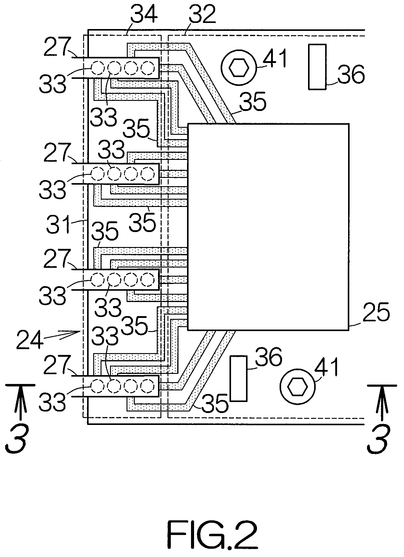
[0032]As shown in FIG. 2, the flexible printed circuit board unit 24 includes a flexible electrically-insulating or isolator sheet 31 according to the present invention. The aforementioned preamplifier IC 25 is mounted on the front surface of the isolator sheet 31. The preamplifier IC 25 is located in a first specific area 32 on the isolator sheet 31. Electrically-conductive materials or pads 33 are likewise formed on the front surface of the isolator sheet 31. The electrically-conductive pads 33 are located in a second specific area 34 separated from the first specific area 32. Wiring patterns 35 are established on the front surface of the isolator sheet 31. The wiring patterns 35 serve to establish electric connections between the individual electrically-conductive pads 33 and the preamplifier IC 25, for example. Electronic components 36 may be mounted on the front surface of the isolator sheet 31 in addition to the preamplifier IC 25. Any other wiring patterns may be established ...

second embodiment

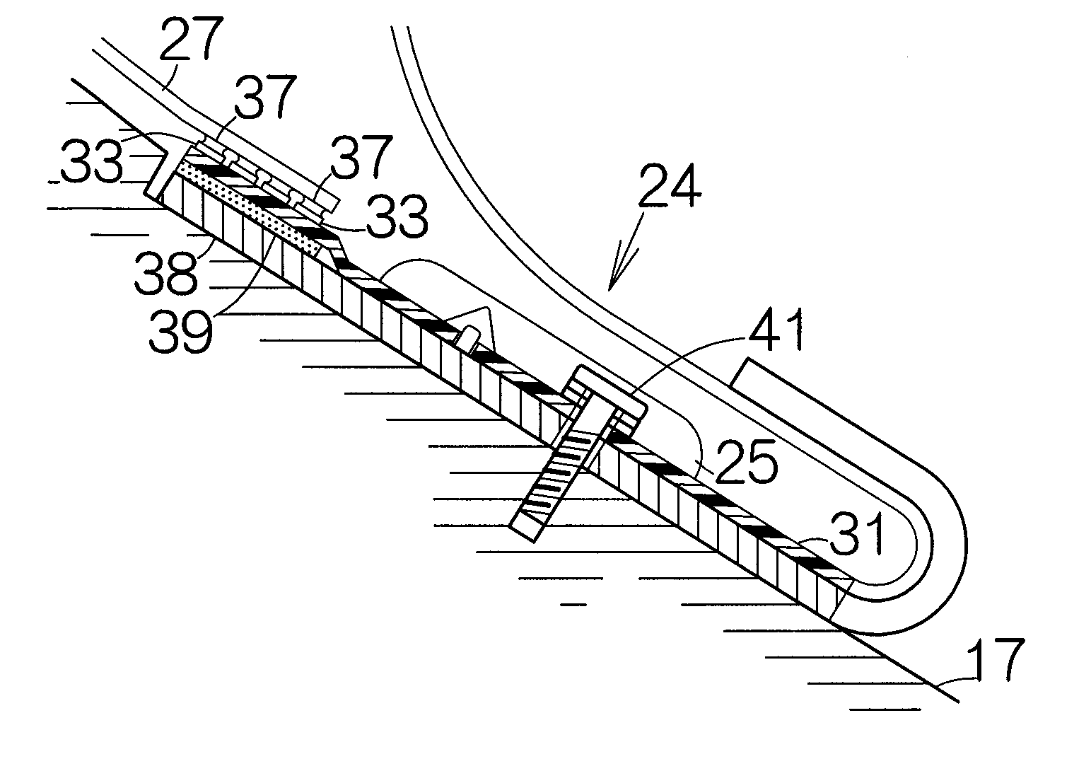
[0041]FIG. 4 schematically illustrates a flexible printed circuit board unit 24a according to the present invention. In this embodiment, a thermally-conductive material or sheet 42 is located on the back of the first specific area 32. The thermally-conductive sheet 42 is distanced from the thermally-insulating sheet 39. The thermally-conductive sheet 42 is interposed between the isolator sheet 31 and the supporting plate 38. The front surface of the thermally-conductive sheet 42 uniformly contacts the back surface of the isolator sheet 31 without a gap. The front surface of the thermally-conductive sheet 42 may be bonded or adhered to the back surface of the isolator sheet 31 with an adhesive. The back surface of the thermally-conductive sheet 42 may be bonded or adhered to the front surface of the supporting plate 38 with an adhesive. Here, the thermally-conductive sheet 42 has a thermal conductivity at least larger than that of the thermally-insulating sheet 39.

[0042]The flexible ...


PUM


Abstract

A thermal component is mounted on the front surface of an isolator sheet within a first specific area. A thermally-conductive material is located on the back surface of the isolator sheet on the back of the first specific area. An electrically-conductive material is located on the front surface of the isolator sheet within a second specific area. A thermally-insulating material is located on the back surface of the isolator sheet on the back of the second specific area. The flexible printed circuit board unit of this type allows heat of the thermal component to efficiently radiate from the thermally-conductive material. An increase in temperature can be suppressed in the thermal component. Heat can reliably stay in the electrically-conductive material when a solder material is applied to the surface of the electrically-conductive material. The solder material is allowed to reliably fuse.

Description

BACKGROUND OF THE INVENTION[0001]1. Field of the Invention[0002]The present invention relates to a recording disk drive or storage device utilized to manage information data based on a recording medium such as a hard disk (HD), for example. In particular, the invention relates to a flexible printed circuit board unit incorporated in such a recording disk drive.[0003]2. Description of the Prior Art[0004]A head actuator having an actuator block is incorporated in a hard disk drive (HDD). A read element and / or a write element are supported on the head actuator. When the actuator block rotates around a specific support shaft, the read and write elements can be positioned right above a target recording track on the magnetic recording disk.[0005]A flexible printed circuit board unit is fixed on the actuator block. A relay flexible printed circuit board is connected to the flexible printed circuit board unit. A preamplifier IC is mounted on the surface of the flexible printed circuit board...

Claims


Application Information

Patent Timeline
IPC IPC(8): G11B5/48G11B33/12G11B21/02G11B25/04H05K1/02H05K1/14H05K1/18H05K3/36H05K7/20
CPCG11B5/4846G11B5/4853G11B5/486H05K1/0201H05K1/0203H05K2201/10689H05K1/189H05K3/0061H05K3/363H05K2201/062H05K1/147H05K1/0281
Inventor KANEKO, HISASHIIWAHARA, HIROYUKIKOMURA, YUKIHIROIZUMI, MITSUHIROFUJIMOTO, SHINJI
Owner FUJITSU LTD
Why Eureka
Try Eureka