
Gauging based on global alignment and sub-models

a global alignment and sub-model technology, applied in adaptive control, process and machine control, instruments, etc., can solve the problems of severely limited range of potential applications for blob analysis, impracticality of subpixel accuracy, and inability to apply subpixel accuracy, so as to reduce the workload of operators

Inactive Publication Date: 2006-01-31
COGNEX TECH & INVESTMENT
View PDF7 Cites 52 Cited by
  • Summary
  • Abstract
  • Description
  • Claims
  • Application Information

AI Technical Summary

Benefits of technology

[0032]According to an illustrative embodiment of the invention, a training image or CAD model of an object is first acquired during a training procedure. A set of points, other shapes or entities (hereinafter referred to as “gauge points”) is then specified using an editor tool. Allowable location tolerances (ranges) can be specified between pairs of gauge points. Each gauge point is then automatically associated with distinctive features such as edges in the training image so that the gauge points can be accurately localized later in a run time image.
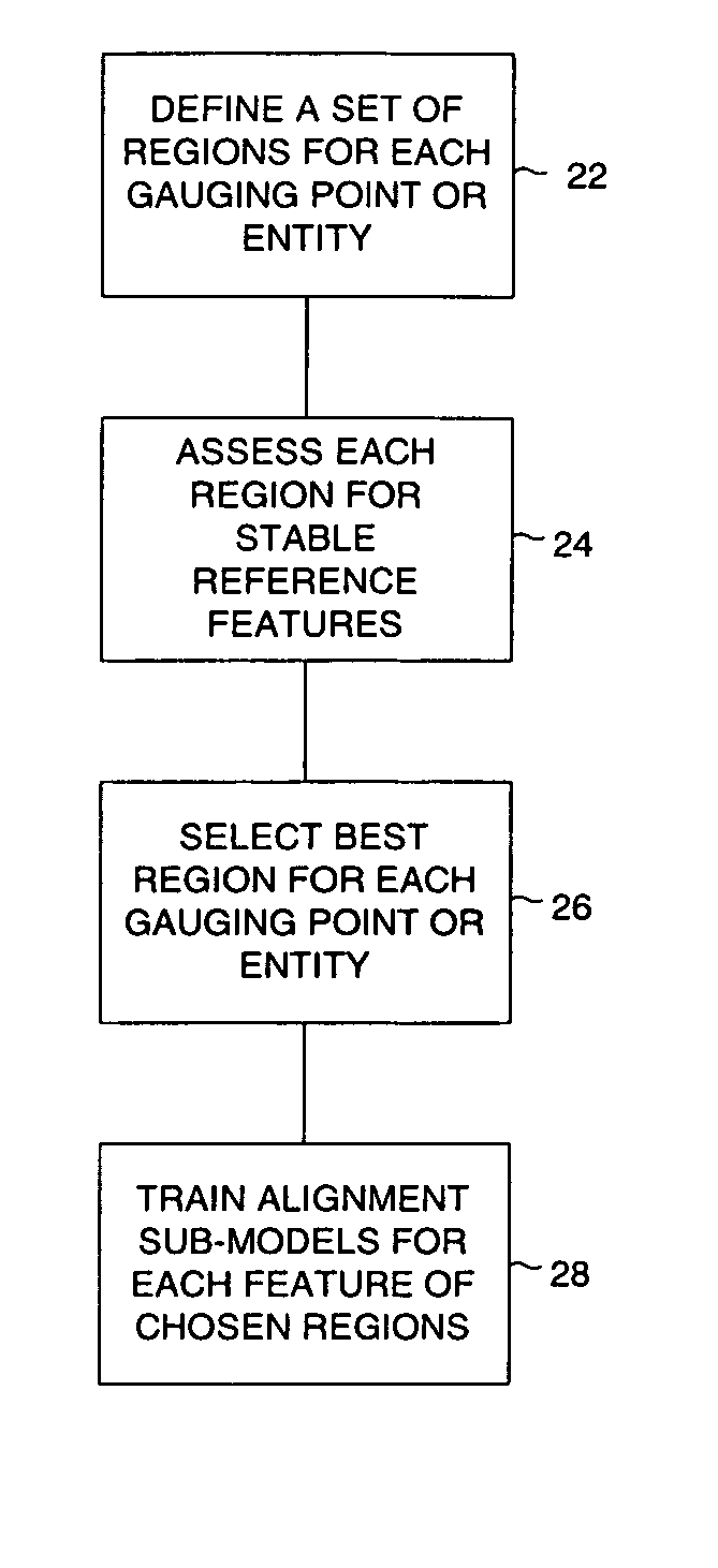
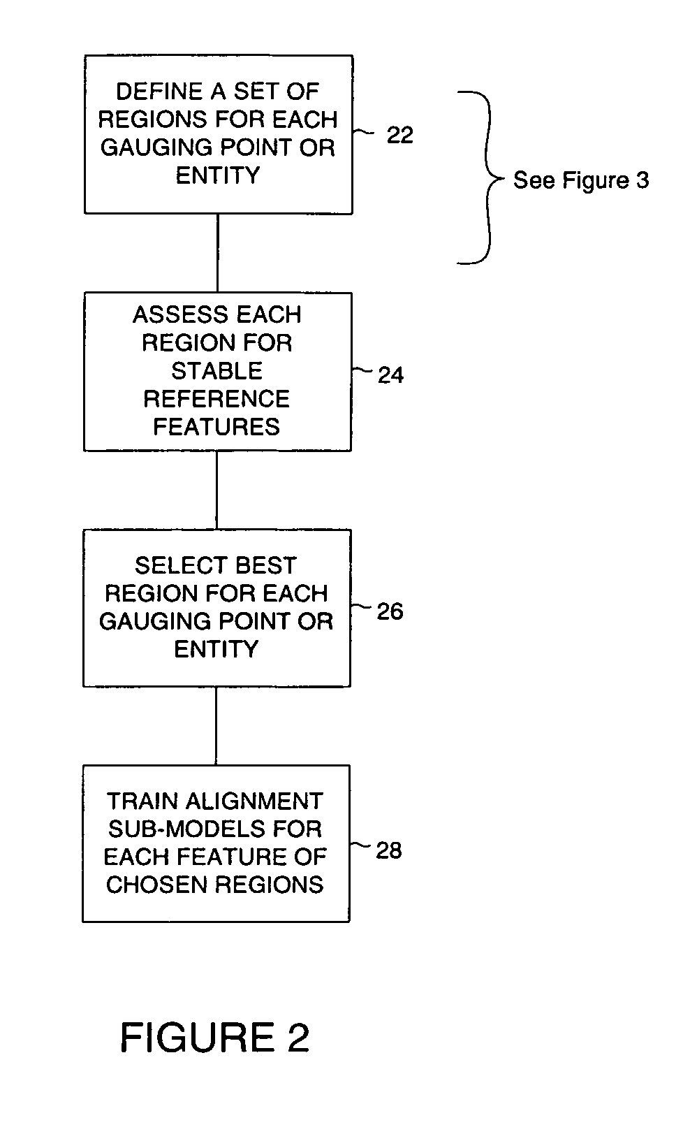
[0037]The present invention features automatic selection of stable features and regions for constructing sub-models by automatically assessing the stability of the relevant features and regions with respect to the alignment tool being used and the selected degrees of freedom. The invention thereby overcomes many limitations of the prior art and provides a mathematically stable way to robustly and accurately measure feature locations despite the absence of nearby stable features in an image. The invention advantageously allows gauging to be performed accurately within the context of a single alignment tool without requiring extensive operator knowledge of machine vision systems and substantially reduces operator workload during the training phase.

Problems solved by technology

However, the presence of touching or overlapping objects in an image and / or noise or image degradation prevents blob analysis tools from discriminating objects for inspection or identification.
The range of potential applications for blob analysis is severely limited because the method of separating objects from backgrounds can only be performed in practice when objects of interest are either entirely brighter or entirely darker than the background.
The thresholding step made subpixel accuracy impractical, by requiring machine operators to choose threshold values, and made results highly susceptible to variations in illumination and object reflectivity.
Unlike blob analysis, however, normalized correlation methods do not have the ability to tolerate and measure variations in orientation and size.
Variations of a few degrees of rotation or a few percent in object size will cause normalized correlation methods to render inaccurate results.
The normalized correlation method also suffers diminished performance when used to identify 3-D objects in an image.
This performance degradation is due to shading variations that depend on illumination direction, target surface orientations and shadows.
These limitations make normalized correlation methods unsuitable for use in typical robotic assembly equipment where recognition of 3-D objects is required.
The task of choosing granularities and selecting features during a training procedure is quite challenging and can be a source of considerable error when humans make these choices.
The linear interpolation approach only works well for rigid 2D objects that translate within the imaging plane, rotate about the line of sight, or scale due to movement along the line of sight.
A known (pre-measured) calibration mapping might be used to extend the capabilities of linear interpolation by correcting for perspective effects; however, non-linear deformations of the objects, such as those due to manufacturing variances, cannot be corrected by such methods.
The method of applying separate alignment tools to find object features disadvantageously requires users to manually choose stable alignment models for the portions of the object from which gauging points are measured.
This method requires the configuration of additional vision tools in an application specific fashion and usually requires extensive knowledge of machine vision, especially when the features of interest do not lie directly on any stable portions.
This technique, however, is limited to locating geometric sub-models of an object when the approximate pose of the object is already known.
Furthermore, it provides no method for automatically determining a set of sub-models for an object so that gauging can be performed.
The human input required by these methods creates opportunity for error and increases the time and expense of making machine vision gauging measurements.

Method used


Image

  • Gauging based on global alignment and sub-models
  • Gauging based on global alignment and sub-models
  • Gauging based on global alignment and sub-models

Examples


Embodiment Construction

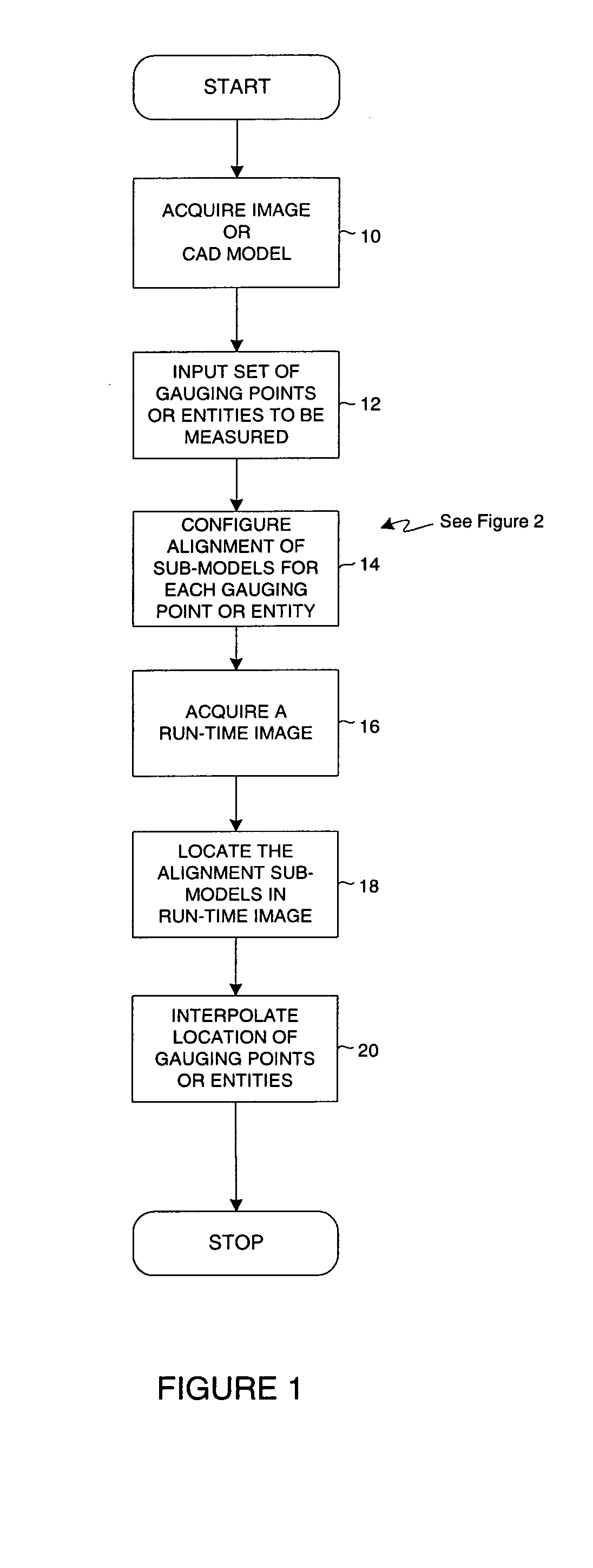
[0046]FIG. 1 illustrates the general steps performed to implement at least one embodiment of the invention. A model acquisition step 10 is first performed in which a training image is acquired or a CAD model is constructed. The training image or CAD model includes gauge points or entities whose location is to be measured. A model typically consists of a spatial arrangement of features that can be related in space to the gauge points or entities. The gauge points or entities may be points, lines or objects whose position is of interest to the user and which have positions that lie within the model. The gauge points or entities are defined by the user during a gauge entity definition step 12 which usually occurs at set up time or training time. The gauge entities can be selected, for example, by selecting points with the cursor in a graphical user interface.

[0047]A configuration of sub-models step 14 is then performed. During the configuration of sub-models step 14, sub-models or feat...


PUM


Abstract

A method for accurately and efficiently determining the location of points or entities in a machine vision image. A set of sub-models are constructed from a global training model representing objects viewed by the machine vision system. The set of sub-models are used to fix the actual location of user selected points or entities. Configuration of the sub-models is automated to ensure that the sub-models contain sufficiently stable features within optimally sized regions without requiring substantial user expertise. Located entities are compared to evaluate compliance with pre-selected tolerances.

Description

FIELD OF THE INVENTION[0001]This invention relates generally to machine vision and more particularly to analyzing image data in machine vision systems.BACKGROUND OF THE INVENTION[0002]Machine vision images are made up of numerical arrays of data defining a color or gray level intensity for each pixel in a two dimensional grid. Industrial machine vision inspection systems typically employ gray level vision. In such systems, the gray level or light intensity level of each pixel is represented by a number from 0 to 255. Image analysis software tools are used to extract meaningful information from raw image data.[0003]Various methods have been developed to recognize patterns, feature edges and contours for recognizing features or objects within an image.[0004]One image analysis tool that is widely known for use in industry is called blob analysis. A blob analysis tool classifies image pixels as belonging to either an object or background and then joins the groups of pixels in each class...

Claims


Application Information

Patent Timeline
IPC IPC(8): G06K9/00
CPCG06K9/6203G06V10/7515
Inventor BACHELDER, IVAN
Owner COGNEX TECH & INVESTMENT
Learn More