System LSI architecture and method for controlling the clock of a data processing system through the use of instructions

a data processing system and clock technology, applied in the field of data processing system, can solve the problems of large drop in the performance of the system lsi, power consumption, increase in power consumption, etc., and achieve the effect of low power consumption and increased work rate or performan

Inactive Publication Date: 2006-01-31
GAIA SYST SOLUTIONS
View PDF37 Cites 5 Cited by
  • Summary
  • Abstract
  • Description
  • Claims
  • Application Information

AI Technical Summary

Benefits of technology

[0024]While a debug unit that can monitor the data being processed by the PU and/or VU is required as part of a system LSI, this debug unit does not need to operate all of the time. Accordingly it is preferable to provide a fifth clock supply unit for supplying, according to a debug signal from outside, a fifth clock signal that has the debug unit operate. By the fifth clock supply unit, the debug unit is in operation according to a debug start signal from outside. When the PU includes a debug function unit that only operates when the debug unit is operational, it is preferable for the fifth control signal to be supplied to this debug fun

Problems solved by technology

However, CPU is the processor core and if the processor core is halted unnecessarily, this can cause a large drop in the performance of the system LSI, though if the processor core is not halted, less of a reduction is made in the power consumption.
If a hard ware control is applied for judging conditions of the processor core and for realizing a halt state of the processor core, more area is required in LSI for such hardware and it is thought that power consumption will increase.
When control is performed by software alone, there is the problem that it is difficult to estimate the period for which the processor core can be halted.
Such operations include conditional branches and interrupt processing, so that an extremely large amount of time and cost are required in order

Method used


Image

  • System LSI architecture and method for controlling the clock of a data processing system through the use of instructions
  • System LSI architecture and method for controlling the clock of a data processing system through the use of instructions
  • System LSI architecture and method for controlling the clock of a data processing system through the use of instructions

Examples


Embodiment Construction

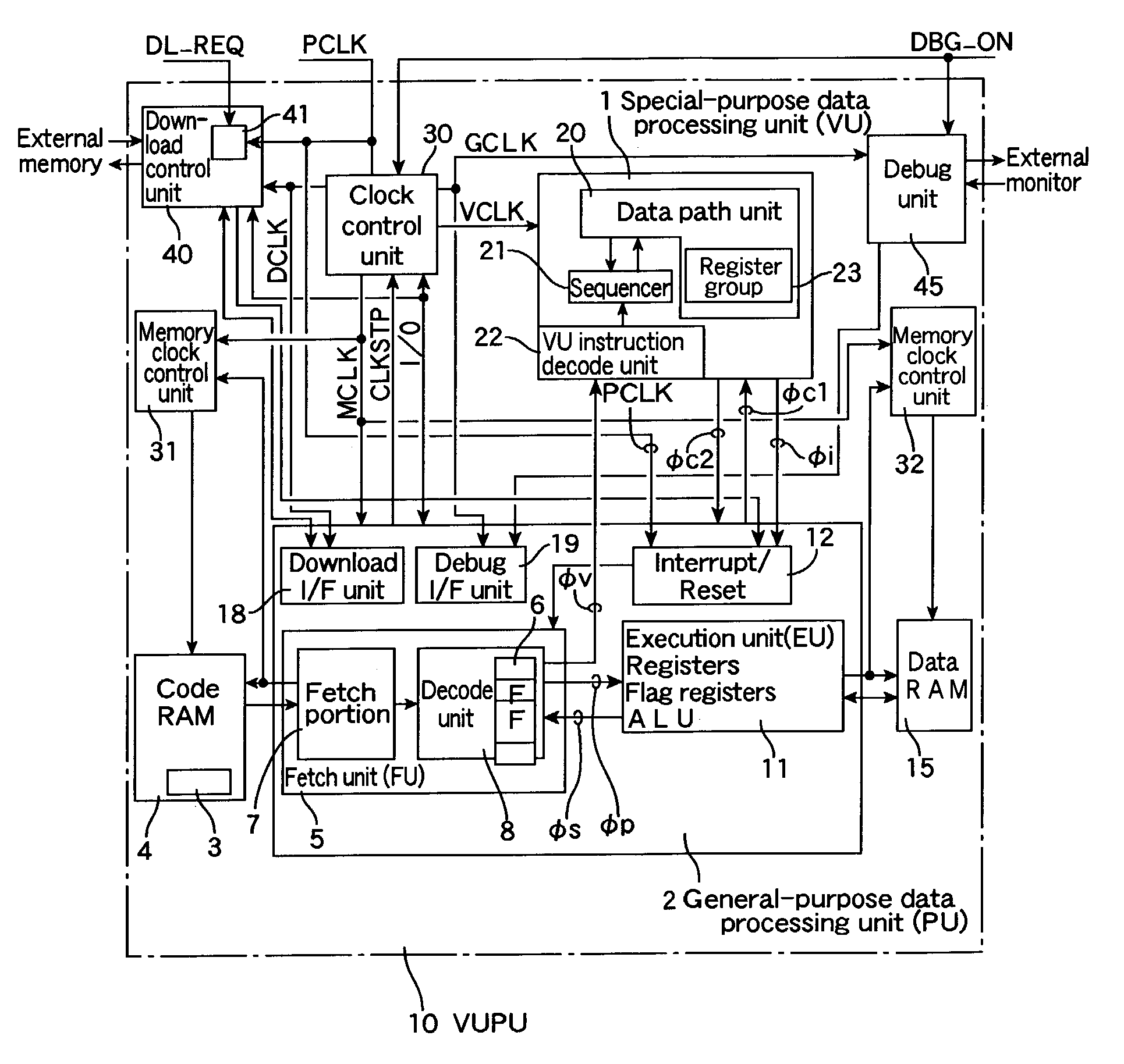
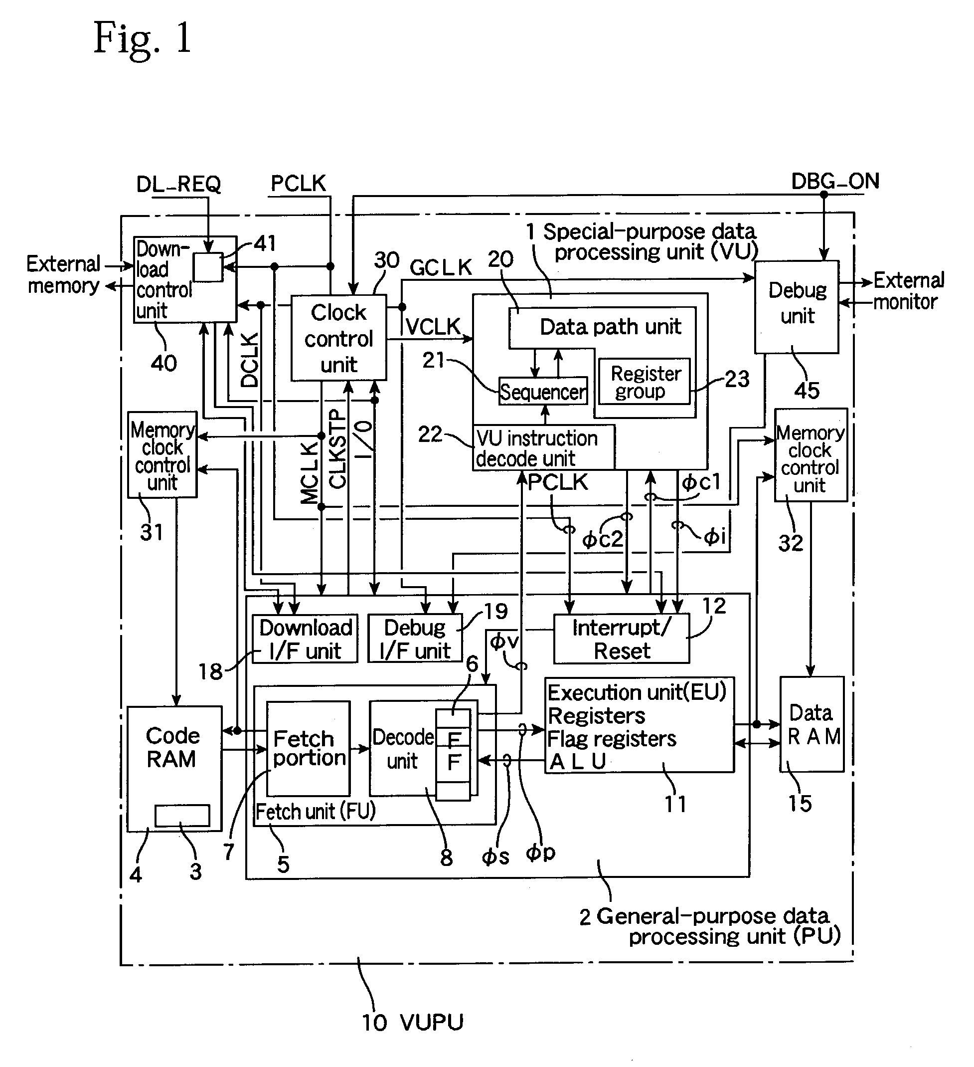
[0035]The following describes an embodiment of the present invention with reference to the attached drawings. A data processing system 10 of the present embodiment shown in FIG. 1 includes a special-purpose data processing unit (a special-purpose instruction executing unit, hereinafter “VU”) 1 that is dedicated to special or specific processing, and a general-purpose data processing unit (a general purpose instruction executing unit or processing unit, hereinafter “PU”) 2 whose construction resembles a standard processor though its detailed functions are different. Accordingly, the data processing apparatus or system 10 is a programmable processor that includes at least a special-purpose circuit.

[0036]The PU 2 includes a fetch unit (hereinafter “FU”) 5 and an executing unit (hereinafter “EU”) 11 that is composed of general-purpose registers, flag registers, computational units (ALU), etc., and has widespread applicability. The FU 5 fetches an instruction from a code RAM 4, which sto...


PUM


Abstract

A data processing system includes a general-purpose data processing unit (PU) including an instruction issuing unit that fetches and decodes an instruction in a program and issues the instruction and an execution unit that executes general-purpose processing according to a general-purpose instruction in the program; a special-purpose data processing unit (VU), including a data path unit for special-purpose data processing, that executes special-purpose data processing according to a special-purpose instruction in the program; and a first clock supply unit for stopping, based on a wait signal that is issued by the VU and shows that the PU is waiting for processing of the VU, a first clock signal for a part of the PU.

Description

CROSS-REFERENCE TO RELATED APPLICATIONS[0001]The present application claims priority of Japanese Patent Application No. 2001-396802, filed in Japan on Dec. 27, 2001, and to Japanese Patent Application No. 2002-307555, filed in Japan on Oct. 22, 2002, the entire contents of which are hereby incorporated herein by reference.BACKGROUND OF THE INVENTION[0002]1. Technical Field[0003]The present invention relates to a data processing system that has a function for reducing power consumption.[0004]2. Description of the Related Art[0005]The ability of mobile appliances, such as mobile phones and mobile terminals, have been greatly expanded together with the advances in information, communication and network technologies. Mobile appliances are assumed to operate on batteries, so that there are stringent demands for the LSIs (Large Scale Integrated circuits) that are central to the constructions of such systems to operate with low power consumption. Japanese Laid-Open Patent Application No. 2...

Claims


Application Information

Patent Timeline
IPC IPC(8): G06F1/04G06F1/32
CPCG06F1/3203G06F1/3237G06F1/3243G06F1/3275G06F1/3287G06F9/3877G06F9/30083Y02B60/1228Y02B60/1221Y02B60/1239Y02B60/1282Y02D10/00
Inventor KITAJIMA, TOSHIAKISATOU, TAKESHI
Owner GAIA SYST SOLUTIONS
Why Eureka
Try Eureka