Well drilling control system

a control system and well technology, applied in the direction of drilling rods, drilling pipes, rotary drilling, etc., can solve the problems of limiting the sensitivity of the well, affecting and increasing the operation cost, so as to improve the accuracy of the directional portion and the accuracy of the directional portion. , the effect of improving the accuracy of the directional portion

Inactive Publication Date: 2006-02-07
AUTO DRILL INC
View PDF4 Cites 31 Cited by
  • Summary
  • Abstract
  • Description
  • Claims
  • Application Information

AI Technical Summary

Benefits of technology

[0026]The addition of an encoder, described in more detail below, can provide an accurate feed back of the rig movements caused by the driller, and thereby provides several additional benefits: (1) it is an integral part of permitting the smooth drilling described above; (2) one is able to provide a display of the amount of footage drilled at any given point in time, how much footage since the last connection was made, and at what rate of penetration is being attained.
[0027]Users of the system of the present invention will be able to automate the process of “time drilling” which is used in virtually all directional and horizontal projects. Time drilling is a process used to start the deviated portion of a directional drilling operation. Through the use of mud motors and deviated sub connections deviation of the hole is started by drilling or moving the deviated bit forward for example, only one inch every five minutes. Currently this is performed by a human “driller” using a wrist watch and crude chalk markings on the “kelly” of the rig.
[0028]The present invention's system allows the directional drilling consultant to program the desired time and distance parameters and know that the work will be performed exactly to specifications resulting in a more accurate start to the directional portion of the project. This is a feature long requested among directional drilling pers

Problems solved by technology

While this invention has application to downhole mud motors, it requires the use of an in-hole tachometer which enhances operation cost.
While such a device is nominally effective as an automatic driller, the use of the Bourdon tubes creates a time lag and limits its sensitivity due to the necessity for pressurization of hydraulic fluid.
This system suffers fr

Method used


Image

  • Well drilling control system
  • Well drilling control system
  • Well drilling control system

Examples


Embodiment Construction

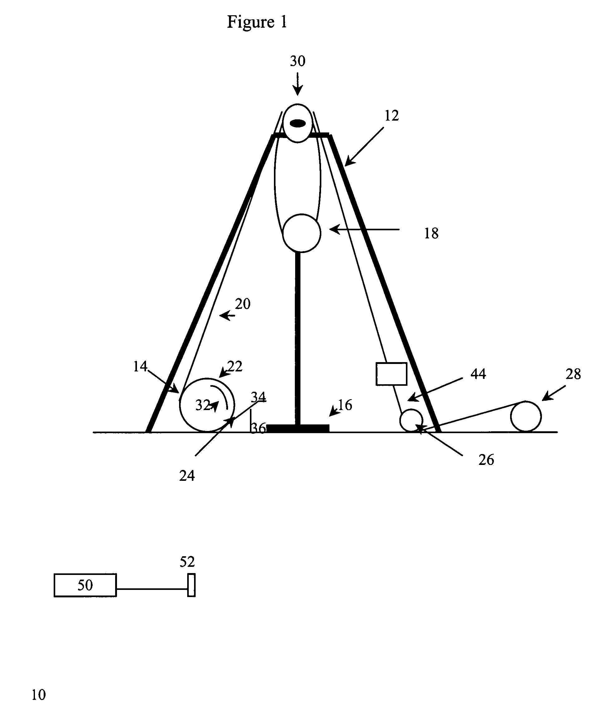
[0037]Referring to the figures, shown therein and referred by the numeral 10 is a draw works control system, constructed in accordance with the present invention.

[0038]For purposes of description, the draw works control system 10 is shown in combination with a conventional rotary drilling rig 12. The rotary drilling rig 12 consists of a draw works assembly 14 and a rotary drilling unit 16 which may be either a top drive or a table drive application. The draw works assembly 14 includes a traveling block 18 suspended from and applying tension to a cable 20. The cable 20 has one end thereof wound on a drum 22, the rotation of which is controlled by a power brake mechanism 24 and a prime mover, e.g. a diesel engine and / or a diesel-electric engine. The other end of the cable 20 is wound around an eccentrically mounted spool 26 and anchored to a storage drum 28. The intermediate portion of the cable 20 is maintained in an elevated position via a crown block 30 in a conventional manner as ...


PUM


Abstract

An improved oil and gas drilling control system which utilizes improved braking and feedback technology which, in turn, permits more precise weight-on-bit control and more smooth transitions of weight-on-bit than any existing technology. In addition, the system also permits more accurate feedback and control with respect to drilling depth, pipe transitions, and rate of penetration than prior systems.

Description

BACKGROUND OF THE INVENTION[0001]1. Field of the Invention[0002]The present invention is directed to methods and apparatus for use with subterranean drilling systems. More specifically, the present invention is directed to systems to maintain a constant and desired weight on a drilling stem to maximize penetration and drilling rates.[0003]2. Description of the Prior Art[0004]In earth drilling, particularly the drilling of oil and gas wells, the control of the drilling operation has usually been accomplished manually. Conventional drilling rigs utilize a draw works which is powered by an engine and operates most of the motor driven portions of the rig. The draw works includes a drum with a drill line wound on it which is fed off to lower drill pipe as the drilling is accomplished. The drill line is looped through a crown block in a double pulley relationship and the end of the line is connected to a fixed point end called the dead line.[0005]As the pipe is lowered into the well durin...

Claims


Application Information

Patent Timeline
IPC IPC(8): E21B19/00E21B44/02
CPCE21B44/02
Inventor RAY, JAMES
Owner AUTO DRILL INC
Why Eureka
Try Eureka