Pre-whirl generator for radial compressor

a generator and radial compressor technology, applied in the field of turbochargers, can solve the problems of affecting engine performance, limited deflection of trailing edge, loss of efficiency, etc., and achieve the effects of reducing the overall mass of the vehicle engine, and reducing the cost of production

Active Publication Date: 2006-02-07
BORGWARNER INC
View PDF13 Cites 47 Cited by
  • Summary
  • Abstract
  • Description
  • Claims
  • Application Information

AI Technical Summary

Benefits of technology

[0020]In all of the above embodiments, the apparatus employed to practice this invention is relatively easy to manufacture and has few moving parts. Accordingly, the present invention provides a performance-enhancing device that is lightweight, adding little to the overall mass of a vehicle engine, and is durable in operation.

Problems solved by technology

When a turbocharger is operated over a wide range of engine speed and load, the turbocharger components function outside the optimum design range and consequently suffer loss of efficiency that adversely affects engine performance.
This complicated arrangement permits limited deflection of the trailing edge of the vane, is prone to jamming and involves excessive friction to operate, and the offset attachment of the vane to the rotating pin permits deflection of the vane in only one direction.
This system is very complicated, has many moving parts, and very limited utility.
It appears to be a complex, expensive structure intended for use on a large expensive turbine engine in which pre-whirl in both positive and negative directions is not considered.
At flow rates below the surge line, a compressor will vibrate violently and cease useful operation.

Method used


Image

  • Pre-whirl generator for radial compressor
  • Pre-whirl generator for radial compressor
  • Pre-whirl generator for radial compressor

Examples


Embodiment Construction

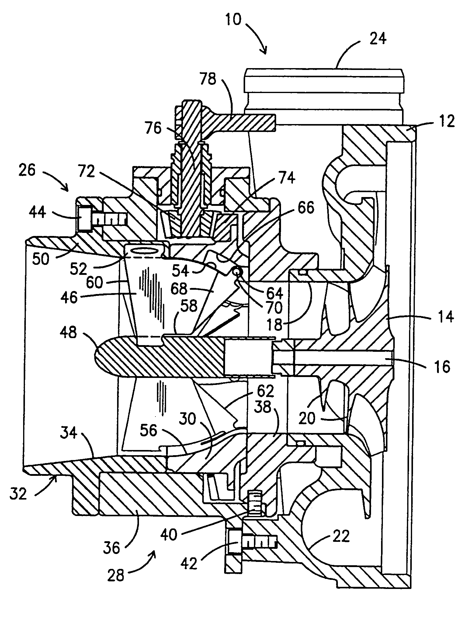
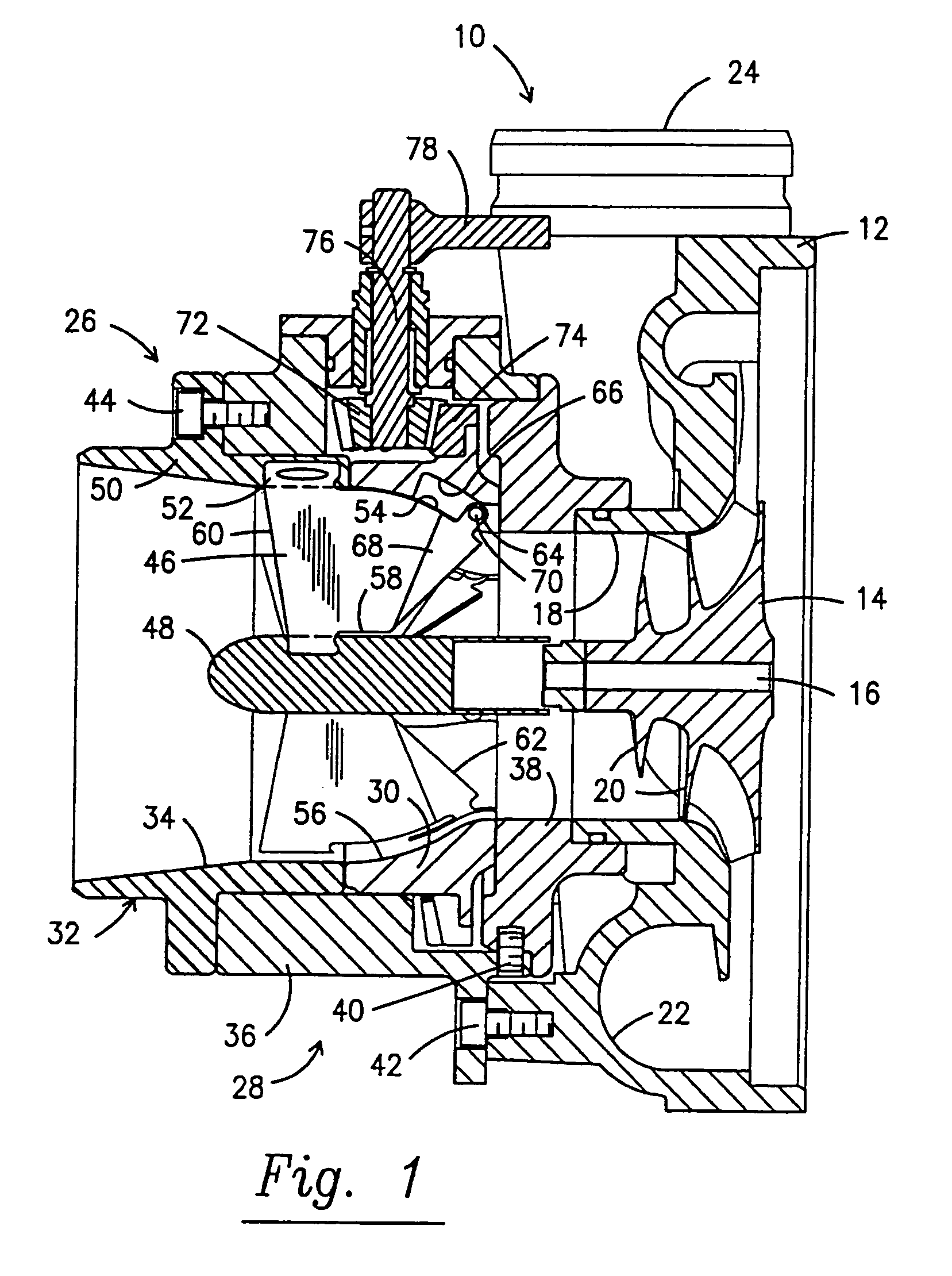
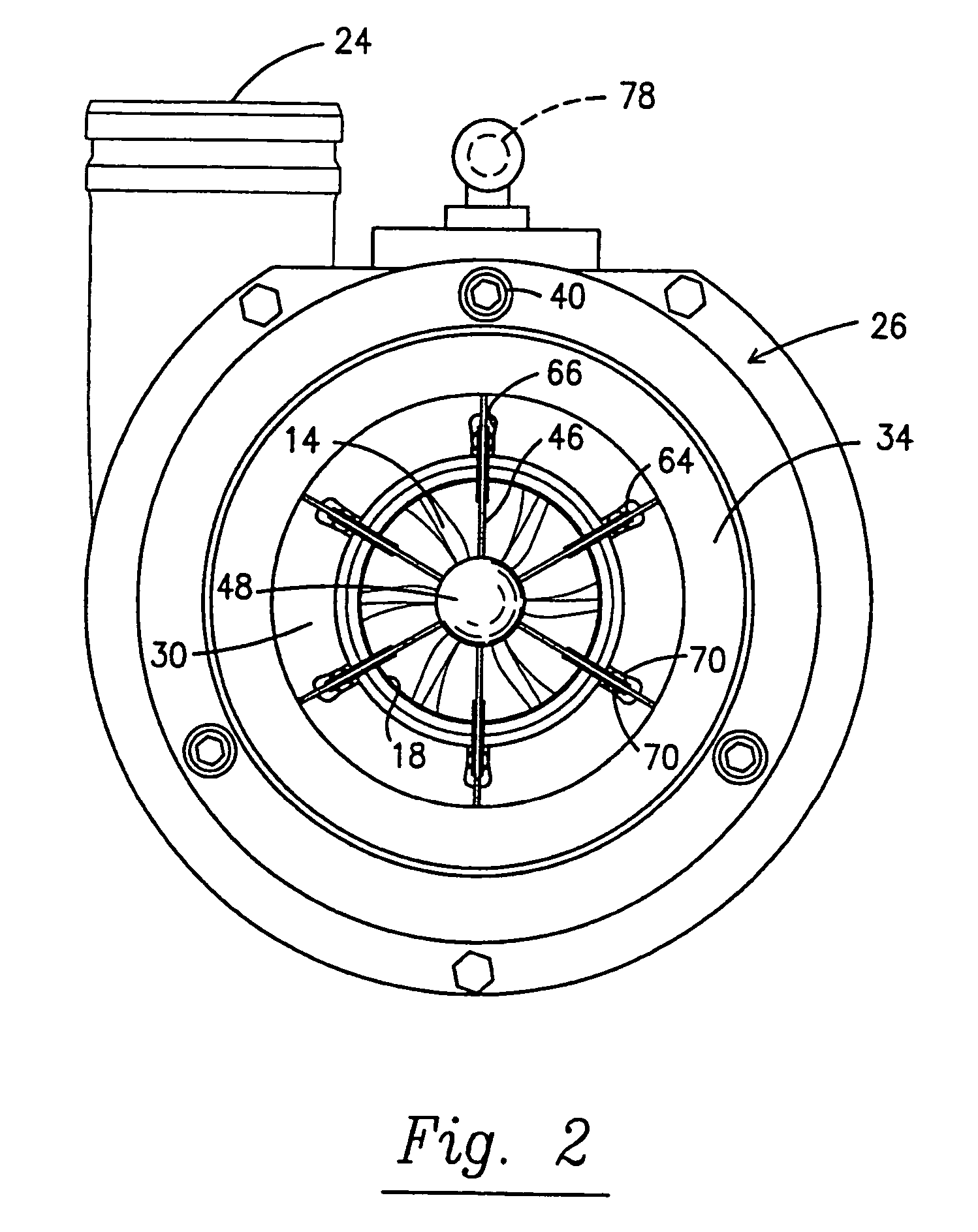
[0062]A turbocharger compressor assembly is generally shown at 10 in FIG. 1 and is comprised of a compressor body 12 which houses a compressor wheel 14 rotatably mounted within the compressor body on a central rotating shaft 16. In a turbocharger, the shaft 16 is normally driven by a turbine (not shown) that is powered by exhaust gases from an internal combustion engine (also not shown) in a conventional and well known manner. The engine is the recipient of compressed air from the compressor assembly 10.

[0063]The compressor 10 is illustrated as a radial centrifugal compressor receiving air at an inlet 18 and driving that air radially over impellers 20 formed on the compressor wheel 14 into a circumferential outlet channel 22 formed in the compressor body 12, which channel leads to the compressor outlet 24. The outlet 24 is in direct communication with the air intake of the internal combustion engine with which the turbocharger compressor assembly 10 is associated.

[0064]For the purpo...


PUM


Abstract

A pre-whirl generating apparatus (26) is provided that employs deformable air deflecting vanes (46) adjacent the inlet (18) of a radial air compressor (12-22), which vanes (46) can be mechanically deformed to generate positive, neutral, or negative pre-whirl flow to the compressor. A minimum number of parts are used to position one or more thin, deformable vanes (46) in the intake channel (34) leading to the compressor inlet (18). In their undeformed position, the vanes (46) do not deflect the incoming air, thereby causing little or no flow restriction. To achieve the desired positive or negative pre-whirl of flow to the compressor (12-22), the trailing edge (62) of the vanes (46) are deflected transverse to the direction of flow in the channel (34) in either the positive or negative direction.

Description

FIELD OF THE INVENTION[0001]The present invention relates to turbochargers for internal combustion engines and more particularly to an arrangement for pre-whirling supply air as it enters the inlet of a radial compressor, which compressor forms a part of the turbocharger.BACKGROUND OF THE INVENTION[0002]Turbochargers are widely used on internal combustion engines, and in the past have been particularly used with large diesel engines, especially for highway trucks and marine applications. In distinction to superchargers, which derive their power directly from the crankshaft of the engine, turbochargers are driven by the engine exhaust gases. Exhaust gases are directed to and drive a turbine, and the turbine shaft is connected to and drives the compressor. Ambient air is compressed by the compressor and fed into the intake manifold of the engine.[0003]More recently, in addition to use in connection with large diesel engines, turbochargers have become popular for use in connection with...

Claims


Application Information

Patent Timeline
Patent Type & Authority Patents(United States)
IPC IPC(8): F01B25/02F04D29/46F01D17/14F01D17/16F02B37/22F04D27/02F04D29/42F04D29/44
CPCF01D17/141F01D17/162F02B37/225F04D27/0246F04D29/4213F05D2260/76Y02T10/144F05D2260/74F05D2220/40F05D2260/4031F05D2250/51Y02T10/12
Inventor SIMON, VOLKERWEBER, MATHIASHOLZSCHUH, CHRISTIAN
Owner BORGWARNER INC
Why Eureka
Try Eureka