Method of manufacturing membranes and the resulting membranes

a technology of microporous membranes and manufacturing methods, which is applied in the direction of membranes, filtration separation, separation processes, etc., can solve the problems of reducing the effective mass of solution heated, reducing process yield, and difficult fine control of the thermal history of large viscous solution, etc., to achieve different profiles and large pore sizes

Inactive Publication Date: 2006-02-07
MILLIPORE CORP
View PDF17 Cites 47 Cited by
  • Summary
  • Abstract
  • Description
  • Claims
  • Application Information

AI Technical Summary

Benefits of technology

[0016]In the process, the polymer solution is thermally assisted under conditions that prevent phase separation. Thermal assisting of the polymer solution can be effected subsequent to shaping the solution, such as by forming a film, tube or hollow fiber of the solution. This invention will be described for convenience in terms of a film or sheet membranes, without being limited thereby. In a preferred embodiment, the formed solution is briefly thermally assisted to generate a temperature profile through the body of the formed solution. The polymer in solution then is precipitated to form a microporous structure such as by being immersed in a bath of nonsolvent for the polymer or by evaporation of solvent, either of these steps optionally in conjunction with contact with humid air before or during phase separation. Higher temperatures and / or longer times effected during the thermal assist step result in larger pore sizes and different profiles in the final membrane product.

Problems solved by technology

Variability in lacquer history can therefore cause reduced process yields.
It can be appreciated that fine control over the thermal history of a large mass of viscous solution is difficult.
An in-line process provides a means for heating the solution as it is transported through a pipeline, thereby reducing the effective mass of solution being heated.
Practitioners have developed complex methods to produce asymmetric membranes from semi-crystalline polymers.
These processes require high temperatures and screw type extruders, increasing process complexity.
Claimed ratios of pore sizes in opposite surfaces ranges from 10 to 20,000 times. This process requires the use of an “unstable liquid dispersion.” Use of such dispersions reduces the control available over the overall process.
These patents teach that differences in lacquer composition and humid air exposures can lead to large structural changes.
Both methods require additional control of the humid atmosphere-polymer solution contact time, humid air velocity, temperature and humidity, thereby increasing process complexity.
The large open volumes, although they may be different in origin from macrovoids, can cause similar mechanical failures in membrane application and are therefore not desirable in applications where high integrity is required.
The presence of these large open volumes is not beneficial in terms of retention, since the diameter of the flow paths are much too large to retain typical solutes or particles filtered by microporous membranes.
Such structures tend to be mechanically weak.
However, to obtain an improvement in flux, it is not sufficient to have a larger pore size on both surfaces, but also that the pore size changes throughout the membrane.
This Increases the complexity of the process because the solvent laden solution must be transported from the heating region to the immersion region of the process while maintaining the desired temperature in a narrow temperature zone above or below the desired temperature so as not to change the final pore size from the designed pore size.

Method used


Image

  • Method of manufacturing membranes and the resulting membranes
  • Method of manufacturing membranes and the resulting membranes
  • Method of manufacturing membranes and the resulting membranes

Examples


example i

[0049]The initial experiment showed that by a short exposure of a cast film, before phase separation but after formation, to heat, the bubble point of a membrane can be changed drastically.

[0050]A 20 w % PVDF solution is made with N-methylpyrrolidone. This film is cast on a polyester sheet and subsequently placed on a hot stage for different times. This heat treated film is then immersed into a methanol bath for 2 minutes and washed with water. Finally the membranes are air dried under restraint.

[0051]

TABLE 1TemperatureIPA peak bubble pointTreatment time(Centigrade)(psi)10 sec501230 sec50202 × 2 sec  50100 (no heat treatment)—54-50 psi

[0052]Surprisingly, the bubble point of the membranes was clearly changed in a relatively small time frame, see Table 1.

example ii

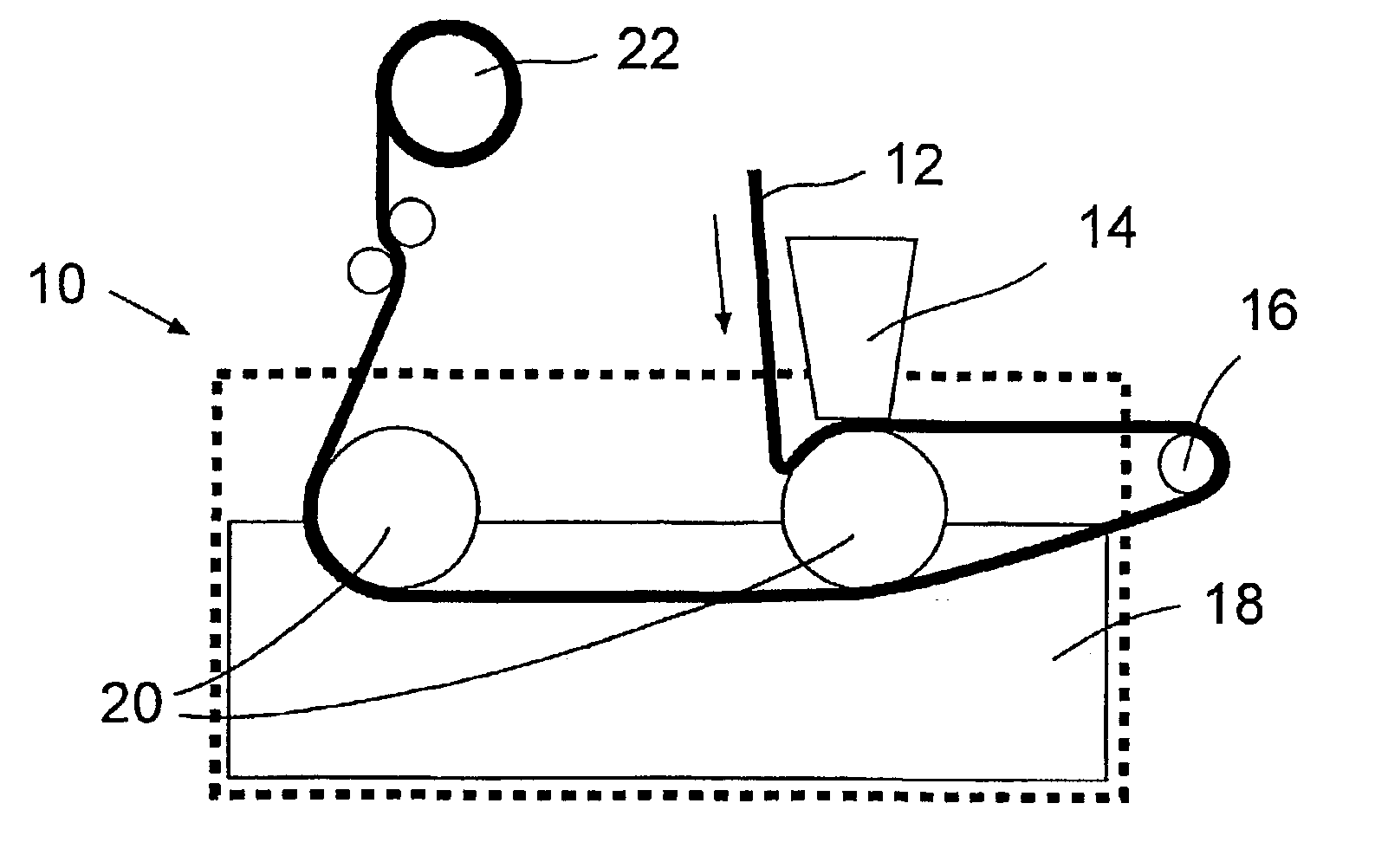
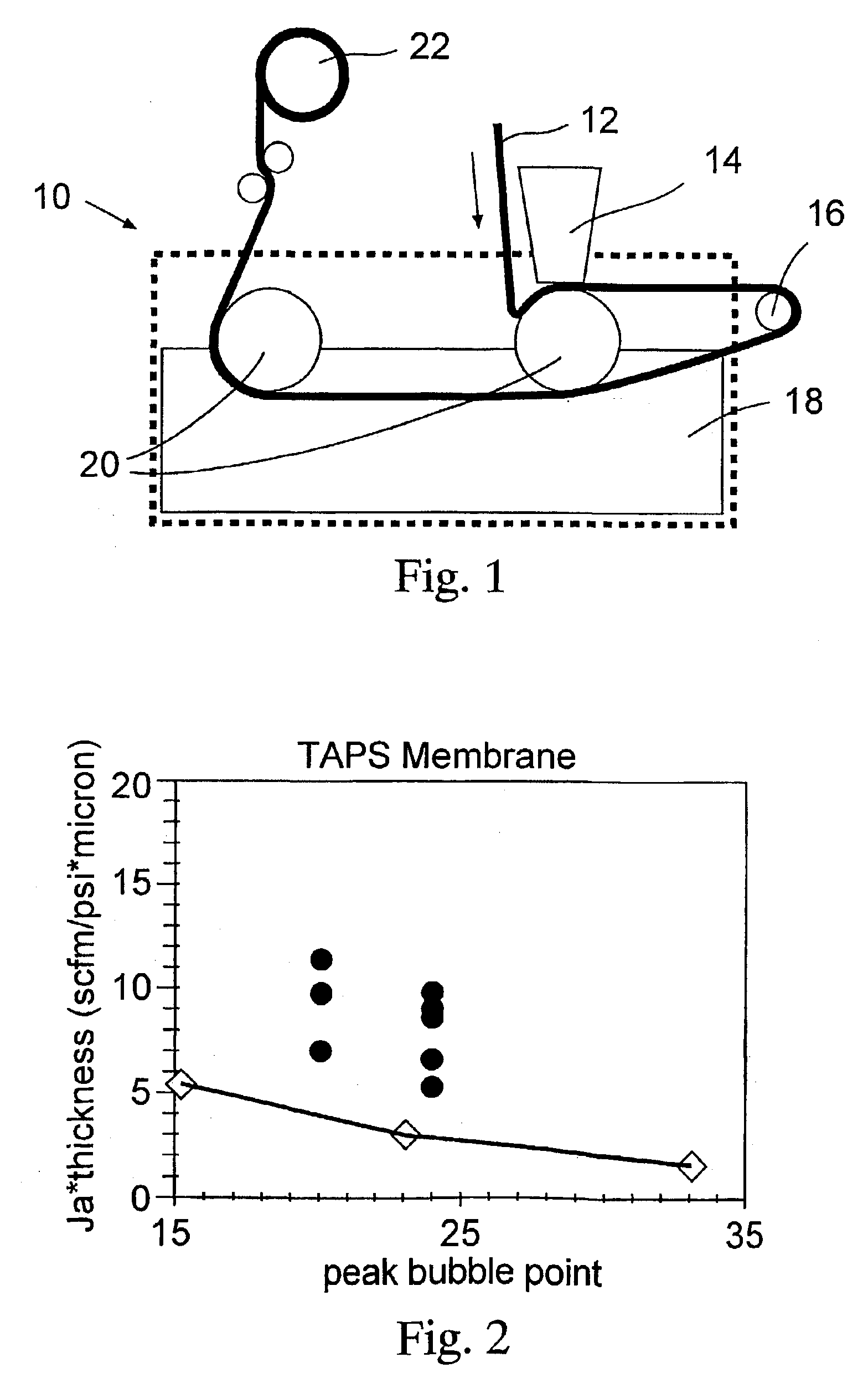
[0053]By using the thermal assisted casting process, membranes with improved fluxes can be made if the exposure time is limited. To obtain better reproducible results, a heated rod was installed on a continuous casting machine. The support belt was conveyed over this rod during casting. An air gap between the heating rod and the coagulation bath was placed to allow the film to cool down to reduce flammability issues in this particular case.

[0054]A 20 w % PVDF solution was made in N-methylpyrrolidone at room temperature. A thin film of polymer solution was cast continuously onto a polyester belt. This cast film was exposed for various times to a heated rod at a controlled temperature. Table 2 displays the time and temperatures of the heat exposure. This heat treated film was quenched into methanol at room temperature and extracted in water, then air dried under restraint.

[0055]

TABLE 2Thickness corrected airTemperatureExposure timeflux(Centigrade)(seconds)Bubble Point(scfm / psi * um)45...

example iii

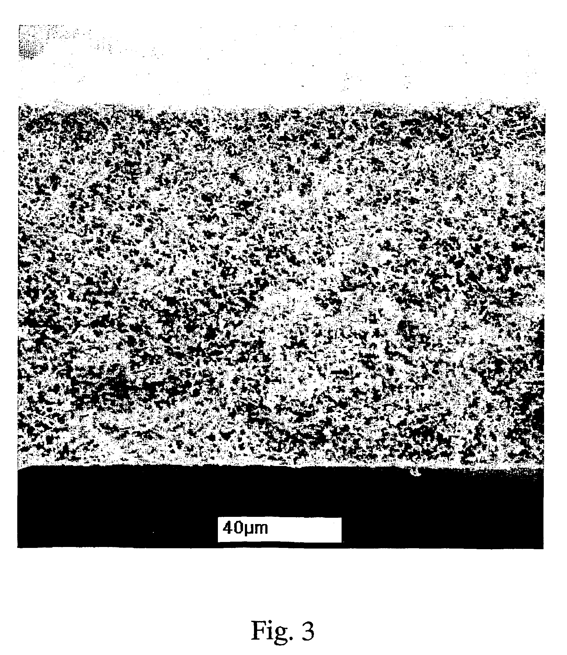
[0058]Asymmetry in PVDF membranes: SEM confirmation

[0059]A PVDF solution was made of 20 w % PVDF In NMP. Membranes were machine cast by exposing a cast film (6 mil gap) to a heated rod for 2 seconds. Two different types of structures were formed using the same lacquer and coagulation procedure: a symmetric, unskinned PVDF membrane with low bubble point (high temperatures) and an asymmetric membrane (at intermediate temperatures). An image of such an asymmetric structure of the present invention is shown in cross section FIG. 3. FIG. 4 shows the top surface of the membrane of FIG. 3 and FIG. 5 shows the bottom surface of the membrane of FIG. 3.

[0060]

TABLE 3Peak Bubble PointTemperature (C.)(psi)43774613

[0061]Unlike what is usually seen with basically symmetric membranes, the bath side of the membrane has a more tight and irregular structure compared to the belt side.

[0062]In all of the examples no macrovoids or filamentous webs were formed, thereby providing a more efficientand effect...


PUM

PropertyMeasurementUnit
sizeaaaaaaaaaa
sizeaaaaaaaaaa
pore sizeaaaaaaaaaa

Abstract

This invention provides a process for making microporous membranes from a polymer solution and the membranes therefrom. A thermal assist, such as heating of the polymer solution can be effected subsequent to shaping the solution, such as by forming a film, tube or hollow fiber of the solution under conditions that do not cause phase separation.. In a preferred embodiment, the formed solution is briefly heated to generate a temperature gradient through the body of the formed solution. The polymer in solution then is precipitated to form a microporous structure. The formation of a wide variety of symmetric and asymmetric structures can be obtained using this process. Higher temperatures and / or longer heating times effected during the heating step result in larger pore sizes and different pore gradients in the final membrane product.

Description

[0001]This is provisional Application No. 60 / 206,622 filed May 24, 2000.FIELD OF THE INVENTION[0002]This invention relates to a process for making asymmetric microporous membranes having a controlled pore size and architecture and to the membranes so produced. More particularly, this invention relates to a process for making these microporous membranes from a polymer solution that is selectively heated under controlled conditions to induce a predetermined membrane architecture formed in a subsequent phase separation step.BACKGROUND OF THE INVENTION[0003]Microporous membranes based on semi crystalline polymers have been previously prepared. Most of the commercial membranes of these polymers are symmetric in nature. The production of such microporous membranes are described, for example, in U.S. Pat. No. 4,208,848 for PVDF and in U.S. Pat. No. 4,340,479 for polyamide membranes. These preparations are generally described to consist of the following steps: a) preparation of a specific a...

Claims


Application Information

Patent Timeline
Patent Type & Authority Patents(United States)
IPC IPC(8): B01D65/00B01D71/28B01D67/00B01D69/02B01D71/00B01D71/34B29C67/20
CPCB01D67/0009B01D67/0013B01D67/0018B01D69/02B01D71/34B01D69/10B29C67/202B01D2325/20B01D2323/08B01D2323/18B01D2323/22B01D2325/022Y10T428/249961
Inventor KOOLS, WILLEM
Owner MILLIPORE CORP
Why Eureka
Try Eureka