Digital loop for regulating DC/DC converter with segmented switching

a digital loop and converter technology, applied in the direction of electric variable regulation, process and machine control, instruments, etc., can solve the problems of large ripple in output voltage, large output current spike, and inability to control output voltage ripple, etc., to reduce output voltage ripple and save die area

Inactive Publication Date: 2006-02-07
SEMICON COMPONENTS IND LLC
View PDF7 Cites 160 Cited by
  • Summary
  • Abstract
  • Description
  • Claims
  • Application Information

AI Technical Summary

Benefits of technology

[0013]Some embodiments of the power control circuit do not use pass transistors, thus saving die area.
[0014]Some embodiments of the invention include a method where the charge pumps are operated in two-phase cycles including a charging phase and a pumping phase. Some embodiments control the power control circuit in both of these phases, thereby reducing the ripple of the output voltage.

Problems solved by technology

However, it can generate high current spikes and a large ripple in the output.
Therefore, the ripple of the output voltage is not controlled and can be quite large.
Further, the loop stability restricts the selection of the external output capacitor and its equivalent series resistance.
The transient performance of the charge pump is limited by the bandwidth of the control loop and can be unsatisfactory.
Finally, the dynamic losses associated with turning the switch array ON and OFF can be high.

Method used


Image

  • Digital loop for regulating DC/DC converter with segmented switching
  • Digital loop for regulating DC/DC converter with segmented switching
  • Digital loop for regulating DC/DC converter with segmented switching

Examples


Embodiment Construction

[0024]Embodiments of the present invention and their advantages are best understood by referring to FIGS. 1–8. Like numerals are used for like and corresponding parts of the various drawings.

[0025]The structure and operation of power control circuits will be described in relation to analog power control circuit 1 of FIG. 4. Then various power control circuits 2 will be described according to embodiments of the invention in relation to FIGS. 5–8.

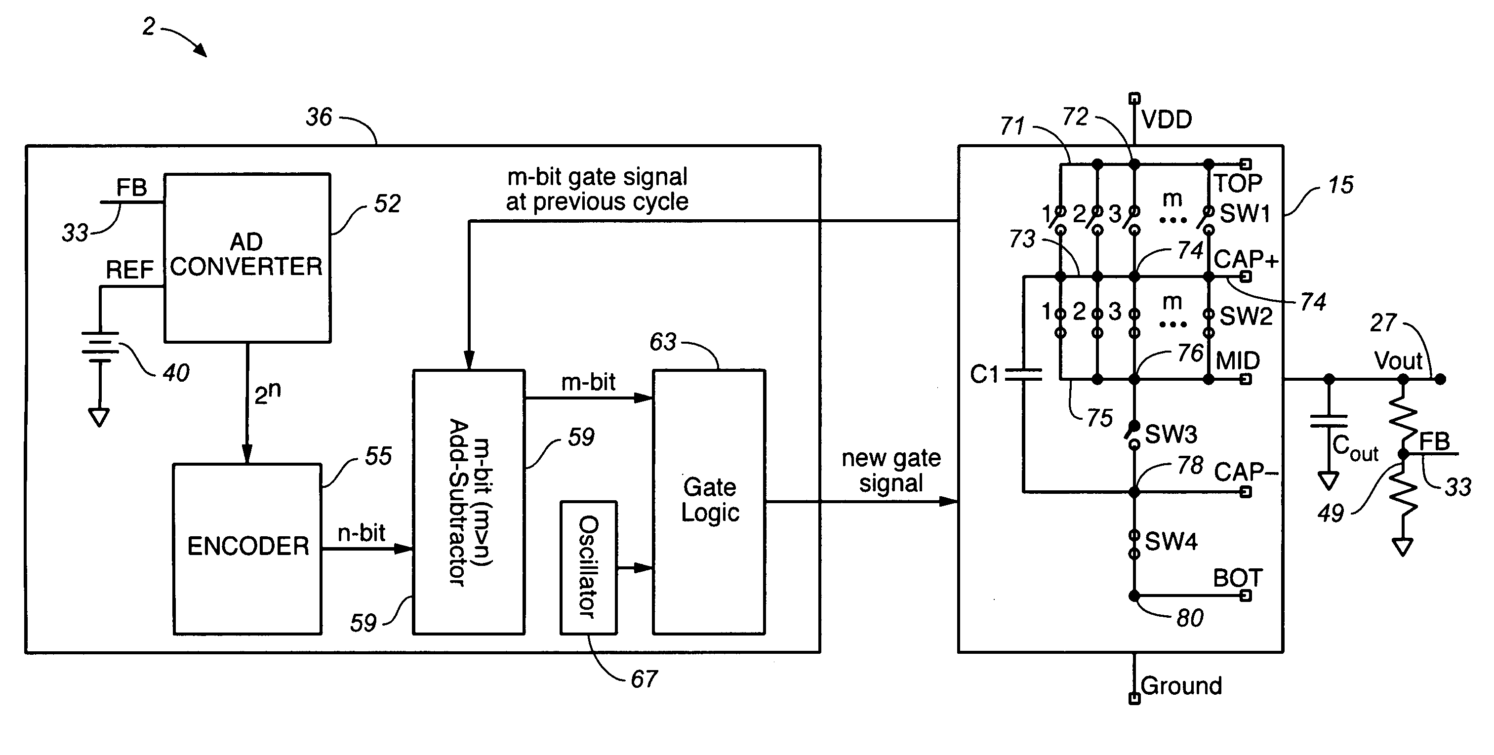
[0026]In power control circuit 1, the regulation of output voltage V—out is achieved in an analog manner by coupling a V—DD supply voltage into voltage regulator block 36. In power control circuit 1 voltage regulator block 36 regulates the fraction of the V—DD supply voltage, which reaches switch array 15.

[0027]Voltage regulator block 36 includes reference voltage supply 40, providing a predefined reference voltage V—ref. In some embodiment the value of reference voltage V—ref can be in the range of about 0.5V to 20V. Voltage regulator block ...


PUM


Abstract

A power control circuit is provided containing a switch array, which includes segmented switches, a flying capacitor, an output voltage terminal, a feedback loop, and a digital voltage regulator block. The digital voltage regulator block includes an A / D converter, an encoder, an add-subtractor, and a gate logic. These power control circuits do not include pass transistors. A method is also provided, where the charge pumps of the power control circuit are operated in two-phase cycles including a charging phase and a pumping phase. The power control circuit is controlled in both of these phases, thereby reducing the ripple of the output voltage.

Description

BACKGROUND[0001]1. Field of Invention[0002]The present invention generally relates to power supplies, and more particularly, to switched capacitor charge pump power supplies for generating a regulated output voltage different from the supply voltage.[0003]2. Description of Related Art[0004]An unregulated switched capacitor DC / DC converter includes a switch array. FIG. 1A illustrates an existing converter topology. This converter utilizes one flying capacitor and four switches. FIG. 1B illustrates another existing topology with two flying capacitors and nine switches.[0005]FIG. 2 illustrates a three terminal device that is equivalent to the switch array. By connecting the TOP, MID and BOT terminals with input, output, and ground in various combinations, step-up, step-down and inverter topologies are created.[0006]FIG. 3 illustrates a 2:1 step-down charge pump. Two-phase non-overlapping clocks are used to drive the switches. In phase 1, the charging phase, switches S1 and S3 are ON. T...

Claims


Application Information

Patent Timeline
Patent Type & Authority Patents(United States)
IPC IPC(8): H02M3/18H02M3/07H02M3/158
CPCH02M3/07H02M2001/0012H02M1/0012H02M3/04H02M3/158
Inventor ZENG, JAMES S.KOTIKALAPOODI, SRIDHARBURGYAN, LAJOS
Owner SEMICON COMPONENTS IND LLC
Why Eureka
Try Eureka