
Method and system for monitoring and profiling an integrated circuit die temperature

a technology of integrated circuits and die temperatures, applied in the field of integrated circuits, can solve problems such as skewing the system clock of microprocessors, adversely affecting component performance, and affecting the performance of components, so as to avoid unnecessary responses

Inactive Publication Date: 2006-02-07
ORACLE INT CORP
View PDF48 Cites 37 Cited by
  • Summary
  • Abstract
  • Description
  • Claims
  • Application Information

AI Technical Summary

Benefits of technology

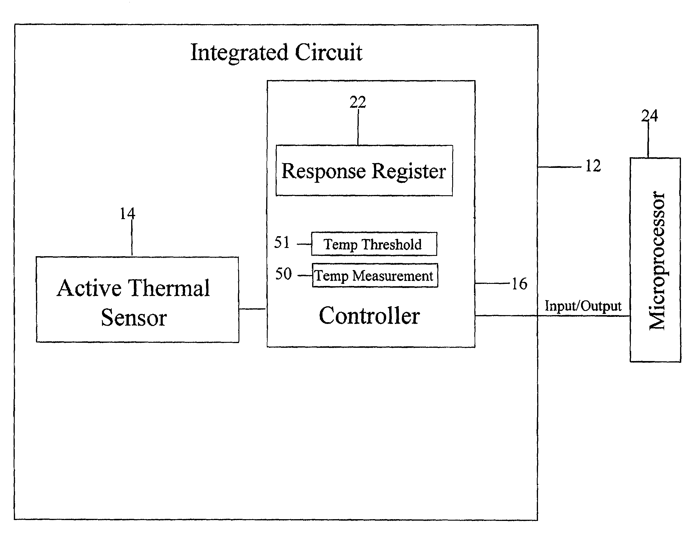
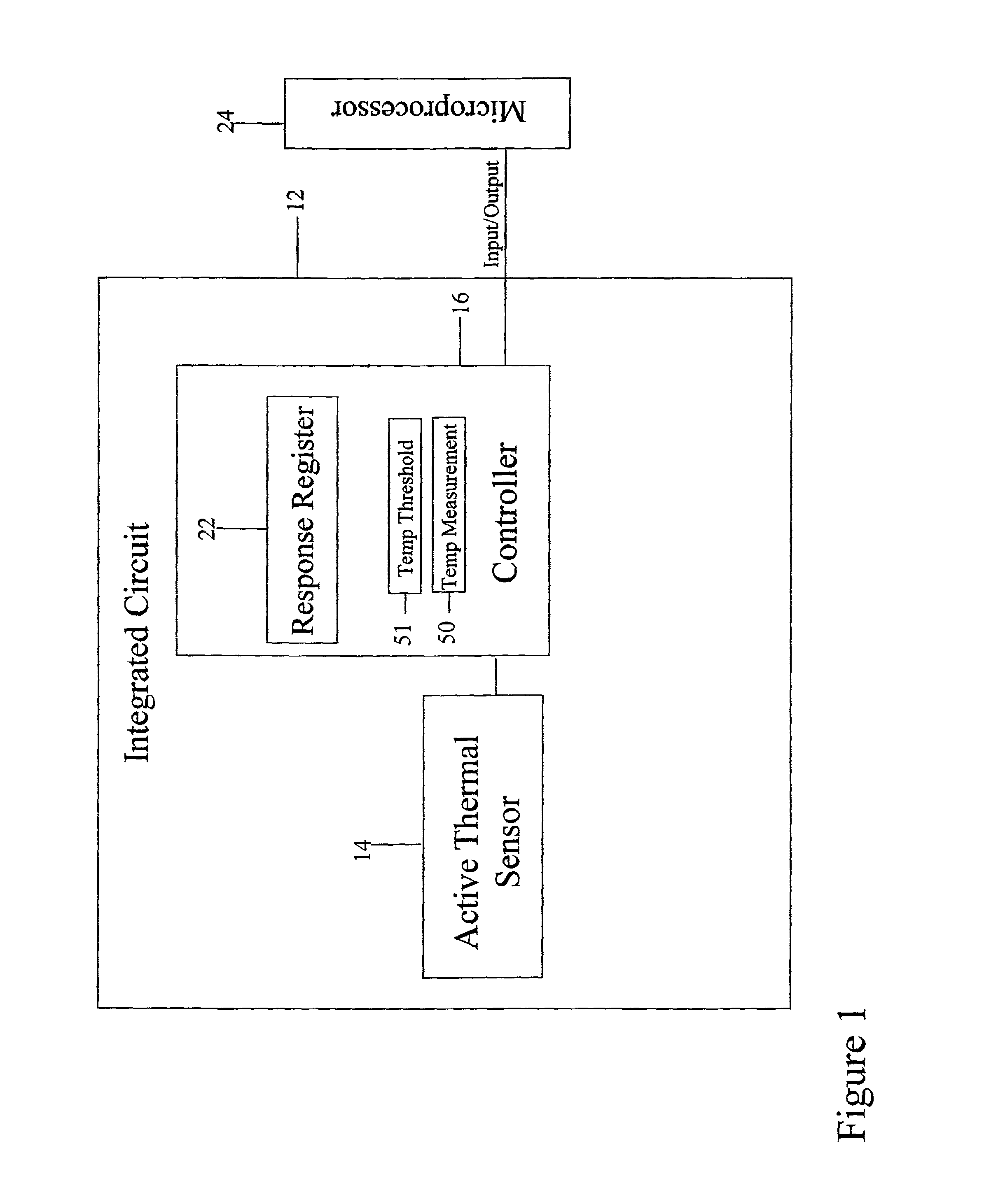
[0007]The above-described approach provides an integrated circuit with a system to monitor the integrated circuit's temperature profile and to detect a temperature rise in a particular area of the integrated circuit before a temperature-related failure occurs. As a result, early detection of an elevated temperature before a temperature-related malfunction occurs allows the system to execute an appropriate response to compensate for the elevated temperature and avoid the temperature-related malfunction. Consequently, temperature abnormalities in an integrated circuit can now be more easily detected. In this manner, active thermal sensors can be placed at multiple die locations in an integrated circuit to accurately track and monitor the thermal gradient of an integrated circuit.
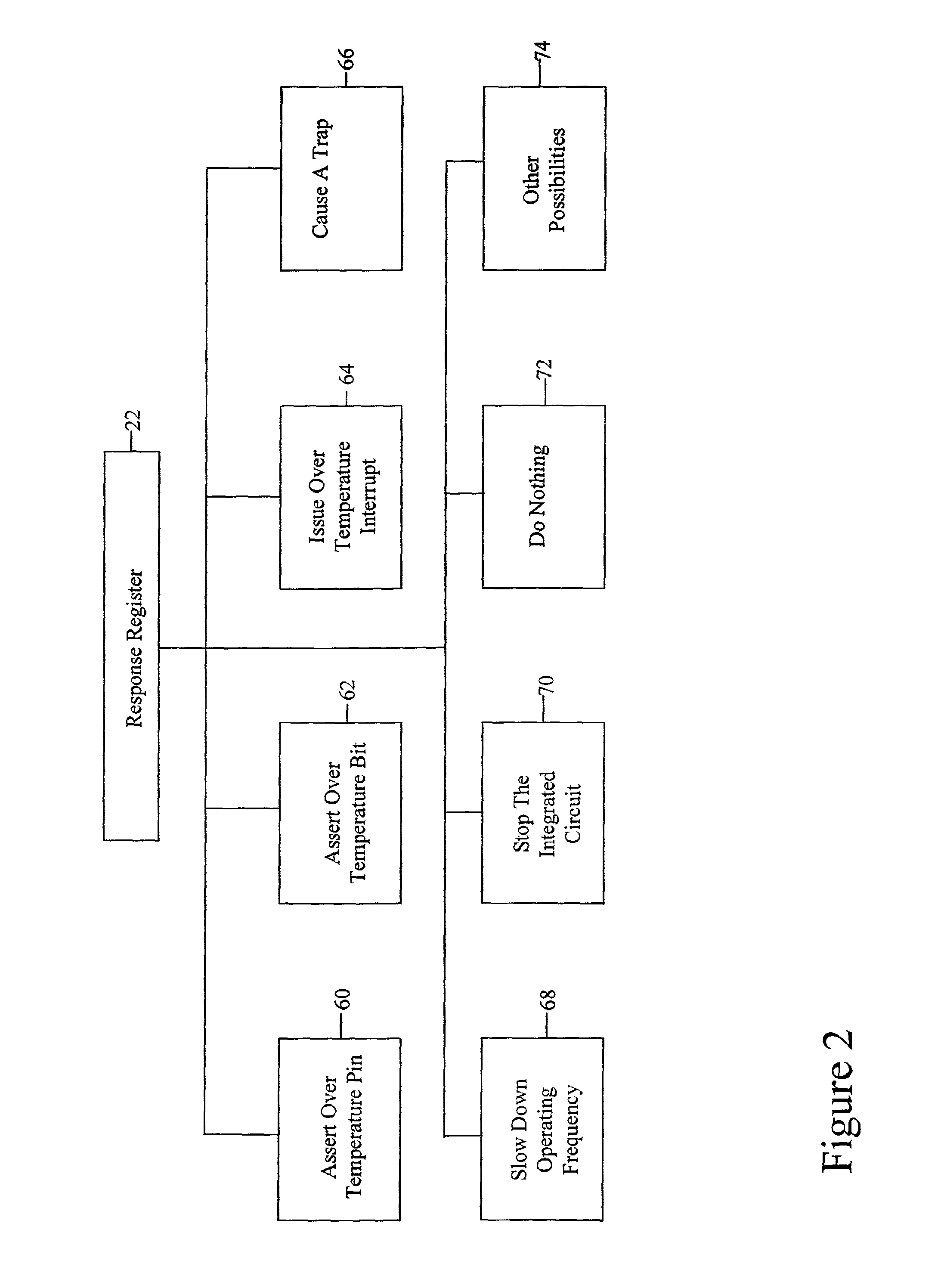
[0009]The above-described approach benefits an integrated circuit, such as a very large scale integration (VLSI) circuit, such as for example, a microprocessor. As a consequence, the integrated circuit is able to monitor and react to an unacceptable die temperature measurement from an active thermal sensor embedded in the integrated circuit thus preventing the integrated circuit from malfunctioning or halting altogether. In addition, accurate temperature profiling of a VLSI circuit, such as a microprocessor can be accomplished as the microprocessor executes various code streams. Moreover, the above-described approach provides a technique to filter erroneous temperature transients and thereby avoid an unnecessary response.

Problems solved by technology

Temperature gradients across the dies of conventional high performance very large scale integration (VLSI) components, such as a microprocessor, can adversely affect component performance.
For example, a temperature variation between two clock driver circuits within a microprocessor often results in a skew in the system clock of the microprocessor.
Moreover, the die of the microprocessor may reach an unacceptable temperature that causes the microprocessor to malfunction or stop functioning.
Unfortunately, the diode provides a temperature reading that can be accurate to about only ±10° C., which is often not accurate enough to provide an early indication of a temperature abnormality.
Given the size and complexity of current and future microprocessors, it is impossible to determine and monitor a temperature gradient across the microprocessor using only a single diode positioned at a location in the die of a microprocessor.
Consequently, any indication that a thermal gradient problem exists in a portion of the integrated circuit go undetected.

Method used


Image

  • Method and system for monitoring and profiling an integrated circuit die temperature
  • Method and system for monitoring and profiling an integrated circuit die temperature
  • Method and system for monitoring and profiling an integrated circuit die temperature

Examples


Embodiment Construction

[0017]For purposes of the discussion below, it is helpful to clarify the meaning of a few terms.

[0018]As used herein, an “active thermal sensor” and an “active calibration thermal sensor” refer to a thermal sensor that requires a source of energy for its operation.

[0019]As used herein, a “passive thermal sensor” refers to a thermal sensor that does not require a source of energy for its operation, for example, an electrical resistor, a diode or other like device.

[0020]As used herein, “calibration” or “calibrate” refers the act or process of determining or measuring one or more temperature measurements while the majority of the circuitry in the integrated circuit is in a non-clocked state.

[0021]The illustrative embodiment of the present invention provides a temperature monitoring system for an integrated circuit that provides one or more die temperature measurements of the integrated circuit to actively monitor and control the die temperature across the integrated circuit. In the ill...


PUM


Abstract

A system and method are provided for sensing a physical stimulus of an integrated circuit. The system and method operate with one or more active thermal sensors embedded in the die of an integrated circuit to provide highly accurate die temperature measurements. The system and method are able to monitor and control the die temperature of the integrated circuit to avoid an integrated circuit malfunction due to an undesirable temperature condition.

Description

REFERENCE TO RELATED APPLICATIONS[0001]The present invention relates to five other applications filed on the same date: An Integrated Temperature Sensor application Ser. No. 10 / 080,037, A Controller for Monitoring Temperature application Ser. No. 10 / 079,475, Quantifying a Difference Between Nodal Voltages application Ser. No. 10 / 078,945, Low Voltage Temperature Independent and Temperature Dependent Voltage Generator application Ser. No. 10 / 078,140 and Temperature Calibration Using On-Chip Electrical Fuses application Ser. No. 10 / 078,760.TECHNICAL FIELD OF THE INVENTION[0002]The present invention generally relates to an integrated circuit, and more particularly, to a system and method to monitor the temperature of an integrated circuit.BACKGROUND OF THE INVENTION[0003]Temperature gradients across the dies of conventional high performance very large scale integration (VLSI) components, such as a microprocessor, can adversely affect component performance. For example, a temperature var...

Claims


Application Information

Patent Timeline
IPC IPC(8): G01K1/08G06F1/20
CPCG06F1/206
Inventor GOLD, SPENCER M.GAUTHIER, CLAUDE R.BOYLE, STEVEN R.HOUSE, KENNETH A.SIEGEL, JOSEPH
Owner ORACLE INT CORP
Learn More