
Adsorptive duct for contaminant removal, and methods

a technology of adsorption duct and contaminant, applied in the field of adsorption elements, can solve the problems that reactive and unreactive silicon containing materials, such as silanes, siloxanes and silanols, can be particularly detrimental to contaminants in some applications

Inactive Publication Date: 2006-02-14
DONALDSON CO INC
View PDF95 Cites 56 Cited by
  • Summary
  • Abstract
  • Description
  • Claims
  • Application Information

AI Technical Summary

Benefits of technology

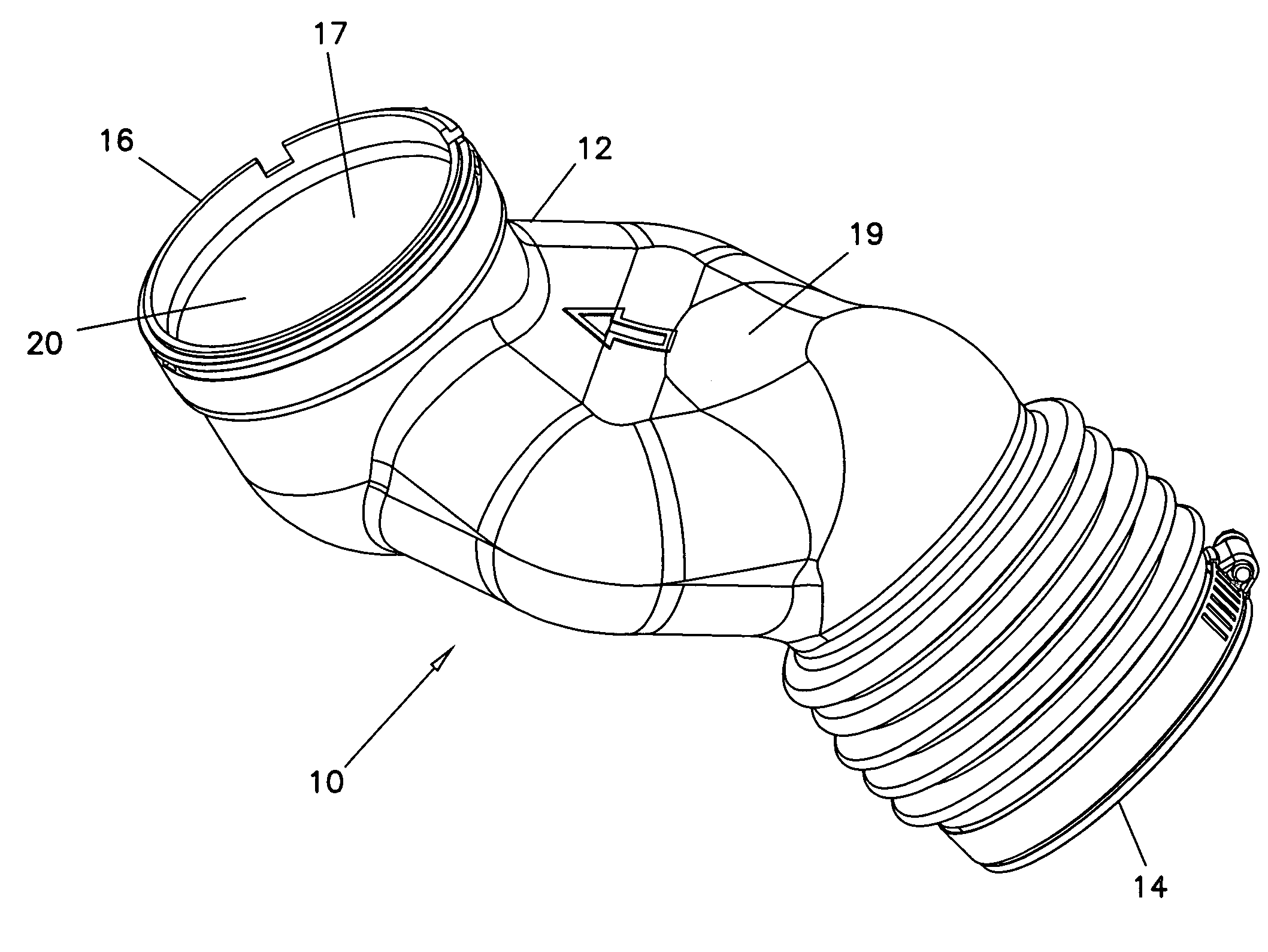
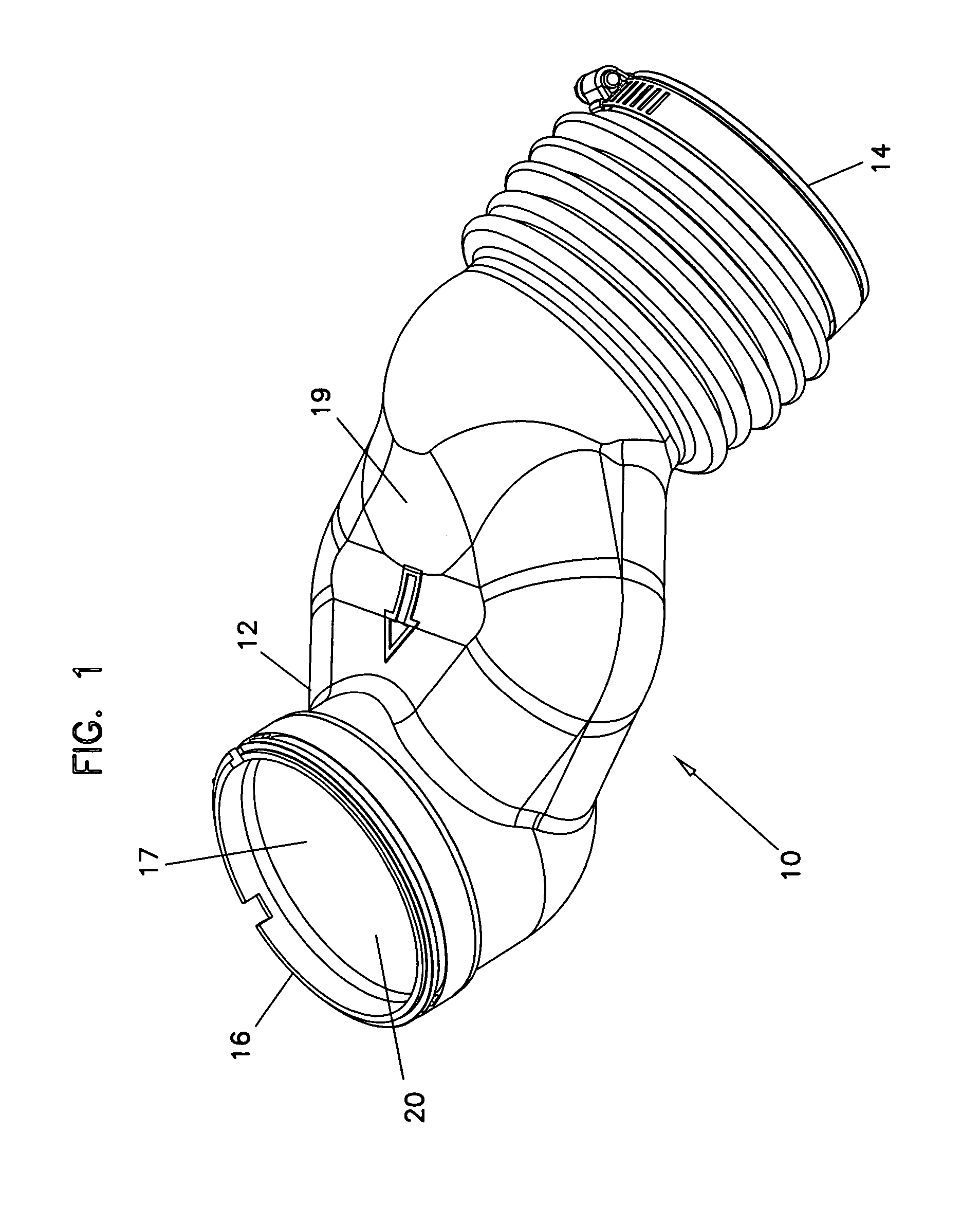
The present invention is about an adsorptive item that can remove contaminants from air or other fluids. It is a duct made of a material that can trap or remove contaminants from the fluid. The duct has a surface that can be reactivated to release the collected contaminants at a later time. The adsorptive material used can be carbon, alumina, zeolites, metal oxides, or ion exchange resins. The duct can be used in various applications where the removal of chemical contaminants is needed, such as in automobile fuel systems or engine induction systems.

Problems solved by technology

Reactive and unreactive silicon containing materials, such as silanes, siloxanes and silanols, can be particularly detrimental contaminants for some applications.

Method used


Image

  • Adsorptive duct for contaminant removal, and methods
  • Adsorptive duct for contaminant removal, and methods
  • Adsorptive duct for contaminant removal, and methods

Examples


first embodiment

[0027]A First Embodiment

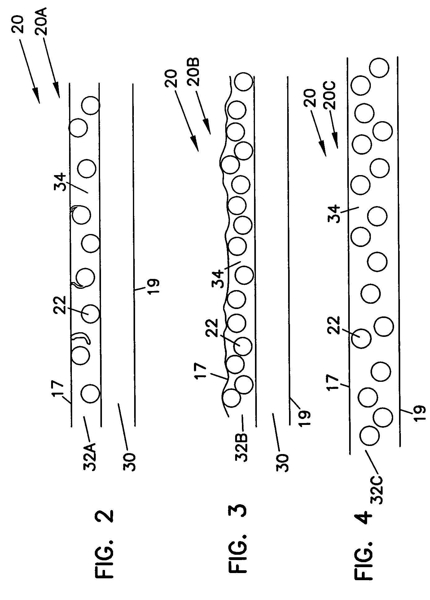
[0028]Illustrated in FIG. 2 is adsorptive region 20A, a portion of duct 10 which includes a plurality of adsorptive material particles 22. Adsorptive region 20A includes a base layer 30 and an adsorptive layer 32A, the adsorptive particles 22 being present within adsorptive layer 32A.

[0029]Base layer 30, which generally forms the overall structure of body 12 and defines outer surface 19, is formed from a polymeric material, such as polyethylene, polypropylene, polyvinyl chloride (PVC), polycarbonate, nylon, polystyrene, poly(methyl methacrylate), thermoplastic elastomers (TPE), and any combinations thereof. Reinforcing materials, such as scrim, fibers and the like may be present within base layer 30. The material used for base layer 30 should have a softening point of no less than about 275° F. Base layer 30 is substantially impermeable to components commonly found in air.

[0030]Adsorptive layer 32A, present adjacent to and attached to base layer 30, defines i...

third embodiment

[0041]A Third Embodiment

[0042]Illustrated in FIG. 4 is adsorptive region 20C, a portion of duct 10 which includes a plurality of adsorptive material particles 22. Adsorptive region 20C has an adsorptive layer 32C having adsorptive particles 22 present therein. For this embodiment, no separate or discernible base layer is present. Rather, adsorptive layer 32C forms the overall structure of body 12, defines outer surface 19, and inner surface 17.

[0043]Duct 10 having adsorptive region 20C can be made by various molding techniques and extrusion techniques. When using molding techniques, the preferred size of adsorptive material 22 is about 100–325 mesh, and the concentration by weight of material 22 in adsorptive layer 32C is about 20–90%, more preferably about 30–60%. In one configuration, the overall thickness of adsorptive layer 32C and of duct 10 is about 3–5 mm; in another configuration, the overall thickness of adsorptive layer 32C and of duct 10 is about 5–10 mm.

[0044]It is under...


PUM

PropertyMeasurementUnit
thicknessaaaaaaaaaa
thicknessaaaaaaaaaa
thickaaaaaaaaaa

Abstract

A duct for passage of air therethough; one particular use for the duct is as a passage for intake air for a vehicle engine. The duct has an interior, adsorptive region that is adapted to remove contaminants from the air stream passing therethrough. The adsorptive region includes adsorptive material such as carbon (usually activated carbon), activated alumina, zeolites, metal oxides or ion exchange resin. The duct inhibits diffusion of uncombusted gasoline back through the duct from the engine, after the engine has been shut off.

Description

[0001]This application is a continuation-in-part application of U.S. patent application Ser. No. 10 / 632,057 filed Jul. 31, 2003, which claims priority under 35 U.S.C. § 119(e) to U.S. provisional application Ser. No. 60 / 400,106 filed Jul. 31, 2002 and entitled “Adsorptive Duct and Methods”. The entire disclosure of these applications is incorporated by reference.FIELD[0002]The present invention relates to an adsorption element for removing contaminants from a gaseous stream, such as an air stream.BACKGROUND[0003]Gas adsorption articles or elements are used in many industries to remove airborne contaminants to protect people, the environment, and often, a critical manufacturing process or the products that are manufactured by the process. A specific example of an application for gas adsorption articles is the semiconductor industry where products are manufactured in an ultra-clean environment, commonly known in the industry as a “clean room”. Gas adsorption articles are also used in ...

Claims


Application Information

Patent Timeline
Patent Type & Authority Patents(United States)
IPC IPC(8): B01D53/04
CPCB01D53/02B01D53/0415Y10S55/05B01D2253/102B01D2253/104B01D2253/108B01D2253/1124B01D2253/206B01D2253/304B01D2253/306B01D2257/2045B01D2257/304B01D2257/406B01D2257/702B01D2257/708B01D2258/01B01D2258/0216B01D2258/0225B01D2259/4508B01D2259/4516B01D2259/4566
Inventor DALLAS, ANDREW JAMESCARTER, STEVEN ALANFLAGSTAD, JORDAN SPENCERDING, LEFEIJORIMAN, JON DENNIS
Owner DONALDSON CO INC
Learn More