Chemical vapor deposition methods utilizing ionic liquids

Inactive Publication Date: 2006-02-14
MICRON TECH INC
View PDF22 Cites 70 Cited by
  • Summary
  • Abstract
  • Description
  • Claims
  • Application Information

AI Technical Summary

Benefits of technology

[0019]The vapor deposition methods of the present invention provide for the vaporization and transport of a controlled mass of precursor molecules in the vapor phase. Due to the unique CVD solvents used in practicing the vapor deposition methods of the present invention, solvent molecules are not transported to the process chamber along with the vaporized precursors. Further, because the vapor deposition methods of the present invention include solvents that have an extremely low or substantially no measurable vapor pressure, the range of precursor materi

Problems solved by technology

However, it is difficult to vaporize a solid at a controlled rate such that a constant and reproducible flow of vaporized solid precursor is delivered to the process chamber.
Lack of control of the rate of delivery of a vaporized solid precursor is (at least in part) due to a changing surface area of the bulk solid precursor as it is vaporized.
The changing rate of vaporization thus results in a continuously changing concentration and non-reproducible flow of vaporized precursor delivered for deposition in the process chamber.
As a result, film growth rate and the composition of films deposited using such techniques are not adequately controlled.
Many precursor materials decompose when quickly heated to such temperatures.
However, many desirable precursor molecules, when heated to a temperature sufficient to maintain a particular deposition rate will simply decompose in the bubbler.
One of the problems associated with this technique is that the high temperatures necessary to quickly vaporize the solution cause solvent and precursor molecules to decompose.
Decomposition of the solvent and precursor molecules within the

Method used


Image

  • Chemical vapor deposition methods utilizing ionic liquids
  • Chemical vapor deposition methods utilizing ionic liquids
  • Chemical vapor deposition methods utilizing ionic liquids

Examples


example

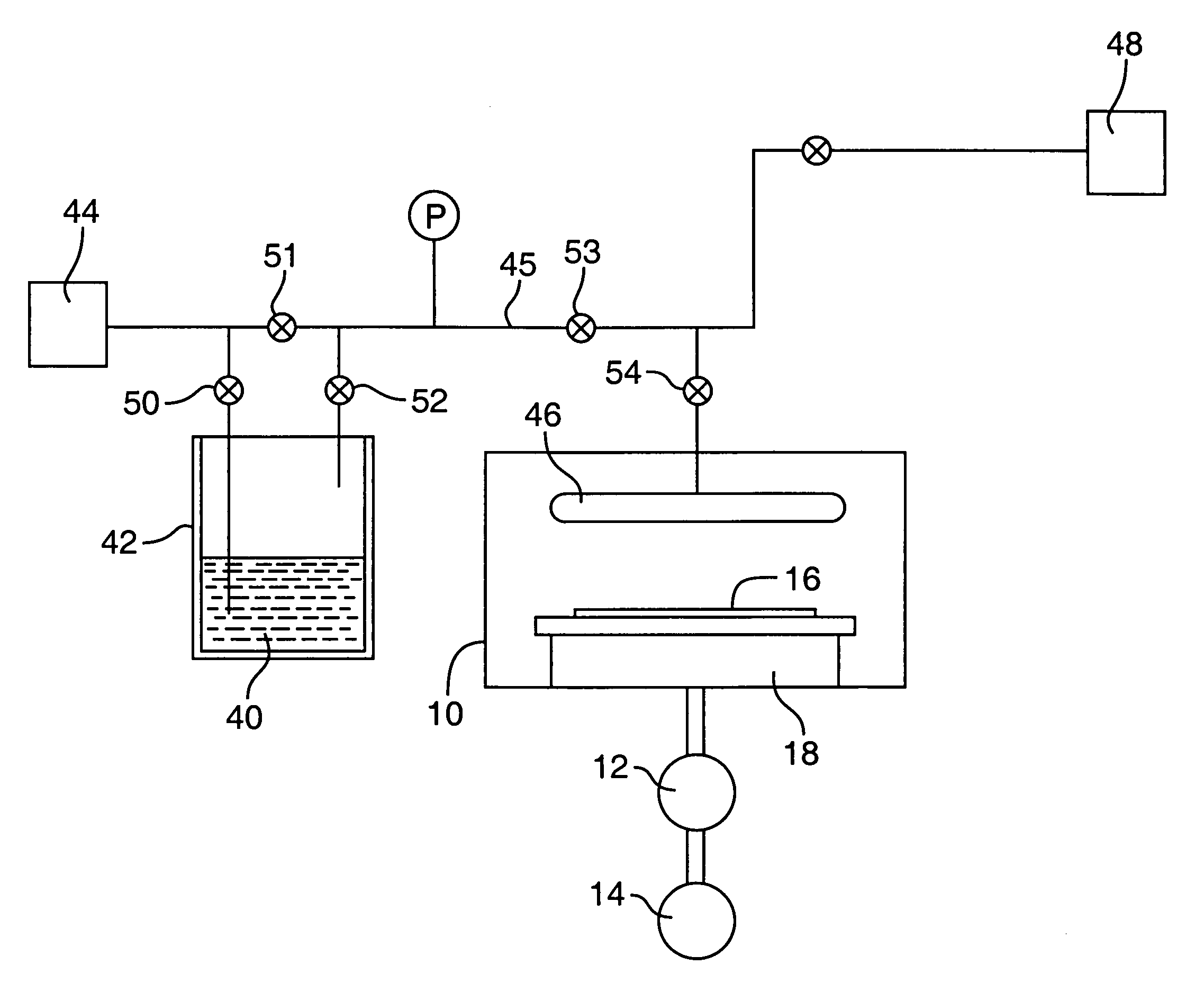
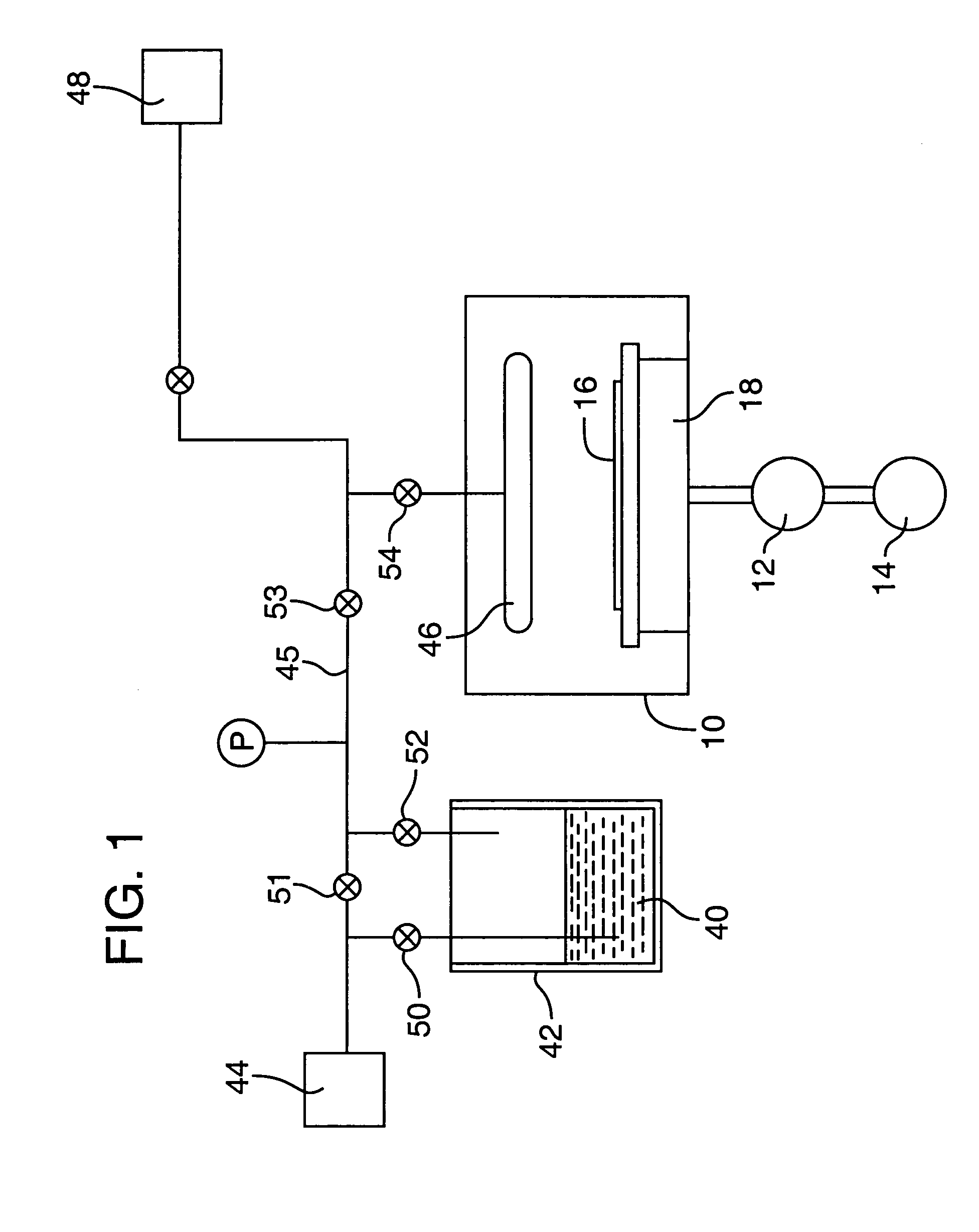
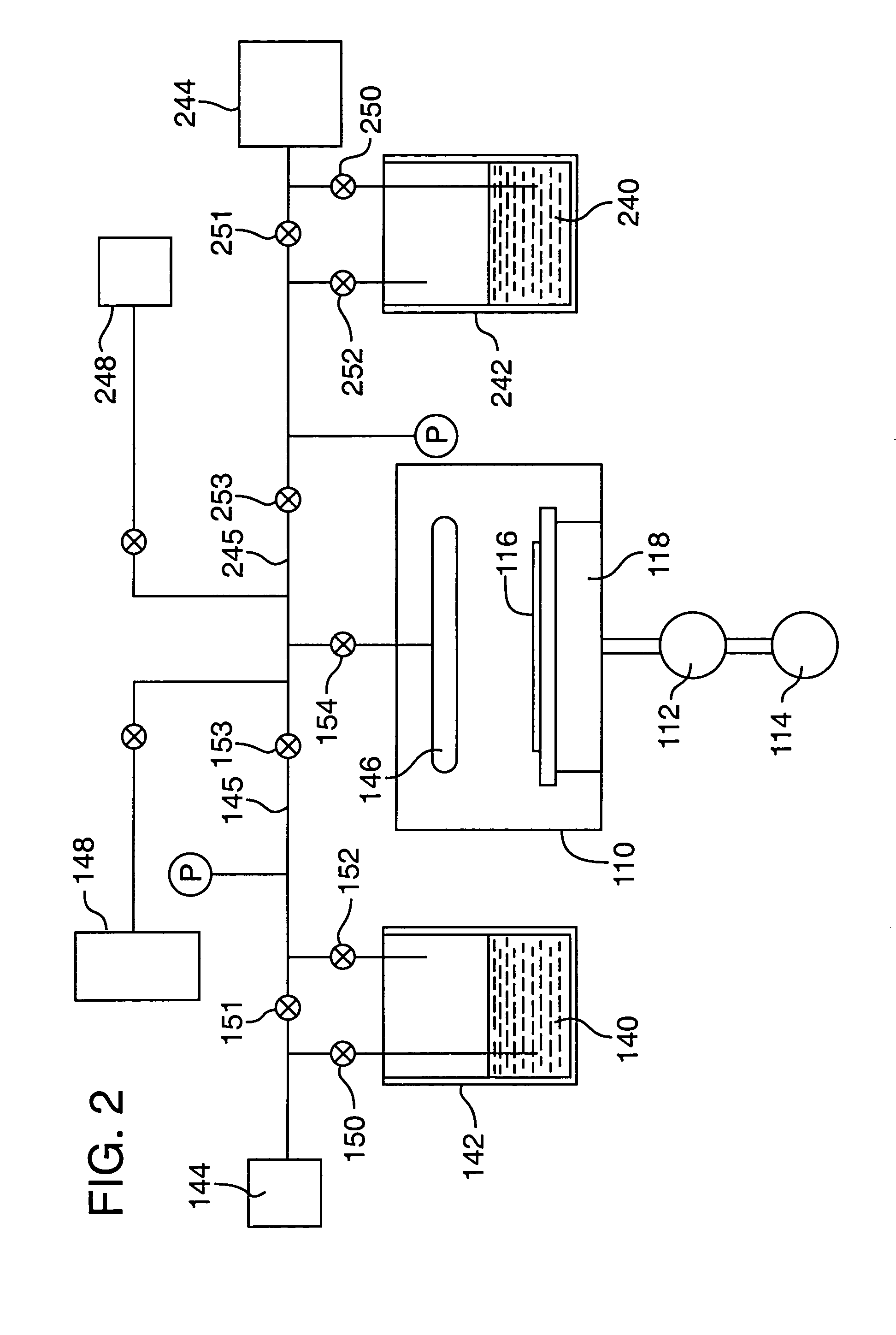
[0048]This is an example of a chemical vapor deposition method of the present invention for the formation of a (Ba,Sr)TiO3 thin-layer on a substrate, using an ionic liquid CVD solvent. Three precursors, Bis(isopropoxide)bis(2,2,6,6-tetramethyl-3,5-heptanedionato)titanium, Bis(2,2,6,6-tetramethyl-3,5-heptanedionato)strontium and Bis(2,2,6,6-tetramethyl-3,5-heptanedionato)barium (all available from, e.g., Strem Chemicals, Inc., of Newburyport, Mass.) are individually dissolved in separate vessels, each vessel containing a quantity of an ionic liquid comprising 1-Ethyl-3-methyl-1H-imidazolium tetrafluoroborate (available from, e.g., Aldrich Chemical Co., Inc., of Milwaukee, Wis.). As much of each precursor as possible is dissolved in the solvent. The solvent solutions having the precursors dissolved therein, are then placed in separate bubbler vessels (e.g., 142 and 242 of FIG. 2; although not shown in FIG. 2, a third analogous vessel and associated delivery means would be required in ...


PUM

PropertyMeasurementUnit
Temperatureaaaaaaaaaa

Abstract

The present invention provides methods and apparatus for vaporizing and transporting precursor molecules to a process chamber for deposition of thin films on a substrate. The methods and apparatus include CVD solvents that comprise ionic liquids. The ionic liquids comprise salt compounds that have substantially no measurable vapor pressure (i.e., less than about 1 Torr at about room temperature), exhibit a wide liquid temperature range (i.e., greater than about 100° C.), and have low melting points (i.e., less than about 250° C.). A desired precursor is dissolved in a selected CVD solvent comprising an ionic liquid. The solvent and precursor solution is heated to or near the precursor volatilization temperature of the precursor. A stream of carrier gas is directed over or is bubbled through the solvent and precursor solution to distill and transport precursor molecules in the vapor phase to a deposition chamber. Conventional deposition processes may be used to deposit the desired thin film on a substrate.

Description

TECHNICAL FIELD[0001]The present invention concerns methods for vapor deposition, and particularly concerns methods for providing volatile precursor molecules to form a thin film on a substrate via vapor deposition.BACKGROUND OF THE INVENTION[0002]Chemical vapor deposition (CVD) is one process for forming thin films on semiconductor wafers, such as films of elemental metals or compounds. CVD involves the formation of a non-volatile solid film on a substrate by the reaction of vapor phase reactants (precursors) that contain desired components of the film. Standard CVD processes use a precursor source in a vaporization chamber of a CVD apparatus. The vaporization chamber is connected to a process (or reactor) chamber wherein a deposition substrate, such as a semiconductor wafer, is located.[0003]CVD (and other thin film vapor deposition) techniques require delivery of a controlled mass of the precursor in the vapor phase. Precise control over the mass of the precursor delivered to the...

Claims


Application Information

Patent Timeline
IPC IPC(8): C23C16/448C23C16/40
CPCC23C16/4482C23C16/409
Inventor UHLENBROCK, STEFAN
Owner MICRON TECH INC
Why Eureka
Try Eureka