Feed forward amplifier system using penalties and floors for optimal control

a technology of optimal control and amplifier, applied in the direction of amplifier, amplifier with semiconductor device/discharge tube, amplifier, etc., can solve the problem that the processing and algorithm may further add a penalty to the cost function, and achieve the effect of reducing the value of the cost function

Inactive Publication Date: 2006-02-14
INTEL CORP
View PDF26 Cites 8 Cited by
  • Summary
  • Abstract
  • Description
  • Claims
  • Application Information

AI Technical Summary

Benefits of technology

[0018]According to another aspect the present invention provides a method for controlling an amplifier system having a control loop comprising a control loop input, a main signal path including an amplifier, and a control loop output. The method comprises determining a loop gain from signal levels at the control loop input and control loop output and comparing the loop gain to a floor value. If the loop gain is greater than said floor value a loop control cost function is s

Problems solved by technology

The processor and algorithm may further add a penalty to the cost function if the cost fu

Method used


Image

  • Feed forward amplifier system using penalties and floors for optimal control
  • Feed forward amplifier system using penalties and floors for optimal control
  • Feed forward amplifier system using penalties and floors for optimal control

Examples


Embodiment Construction

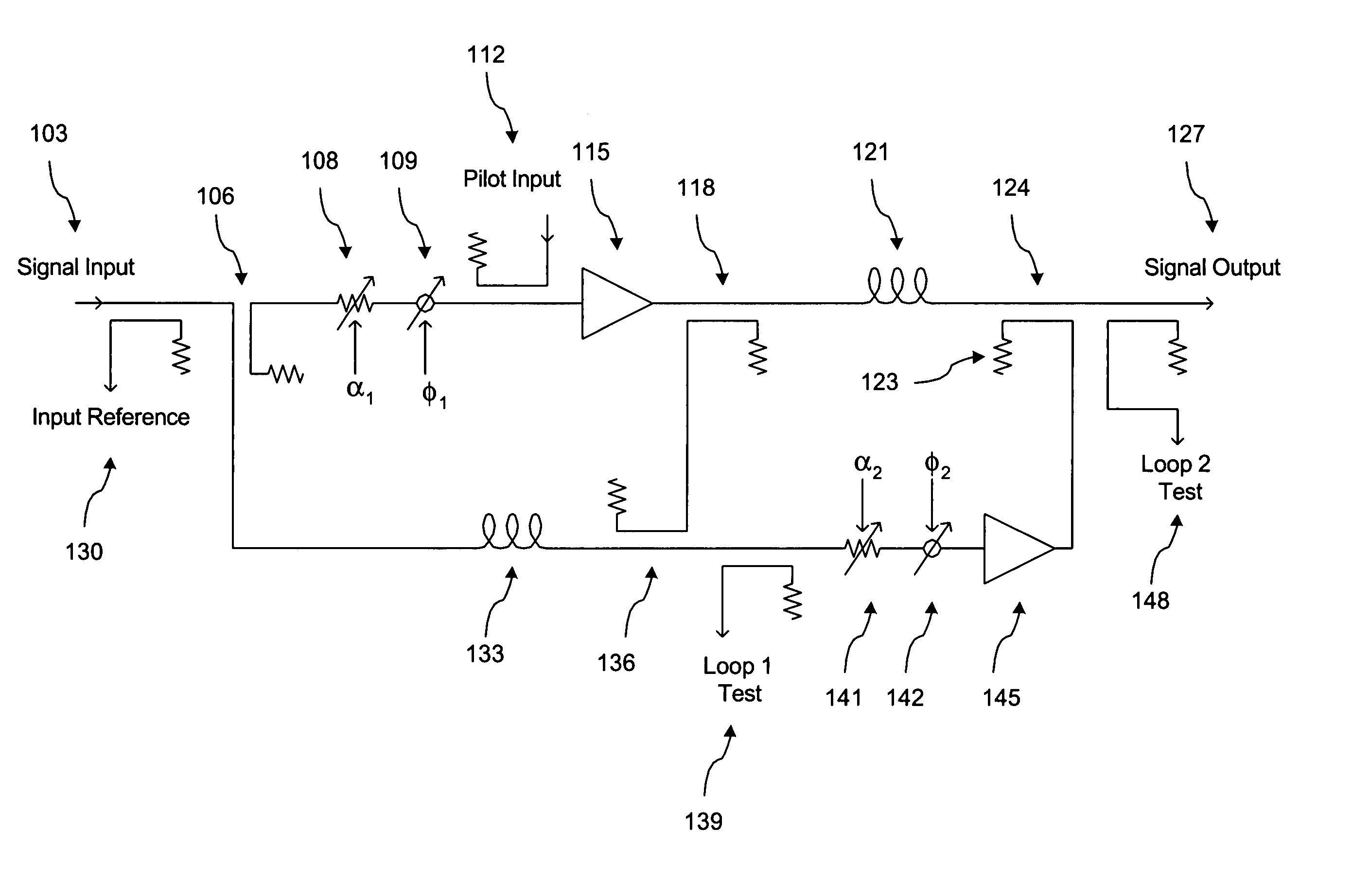
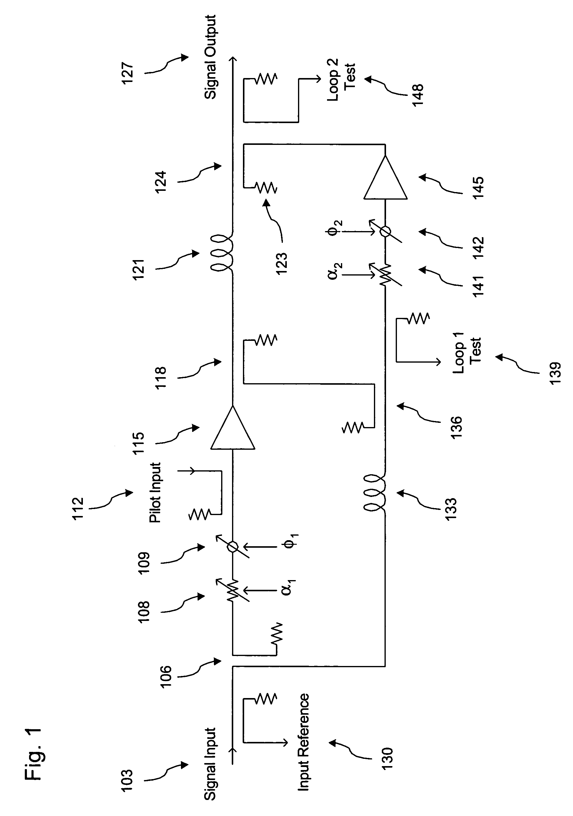
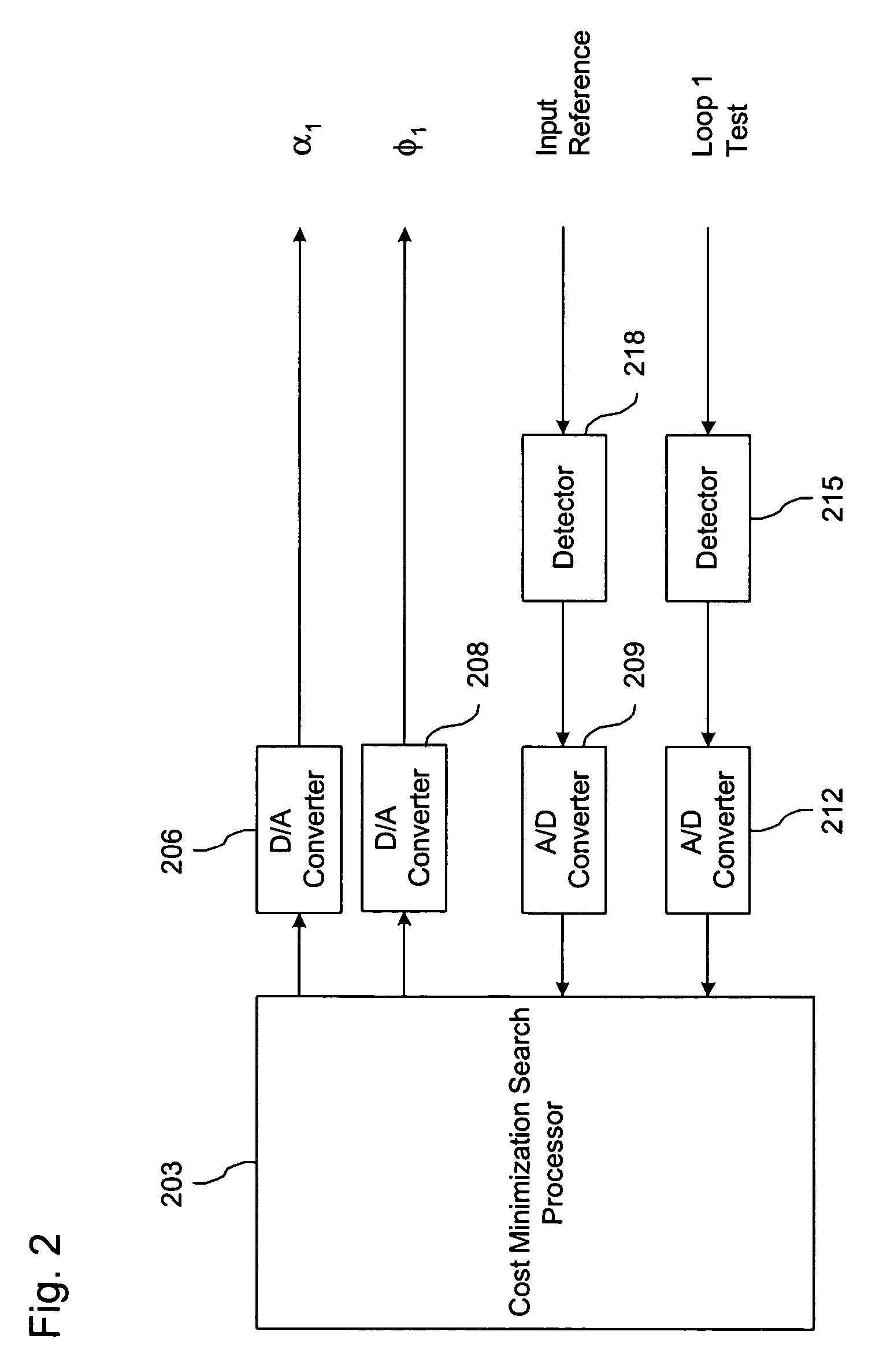
[0031]A block diagram of the feed forward compensated power amplifier (PA) system in accordance with a preferred embodiment of the present invention is shown in FIGS. 1 and 2. FIG. 1 illustrates the basic feed forward amplifier and FIG. 2 illustrates the controller.

[0032]As shown in FIG. 1, the feed forward amplifier has a conventional architecture employing two control loops. Loop 1 comprises signal input 103, sampling coupler 106, gain adjuster 108, phase adjuster 109, (optional) pilot input 112, main amplifier 115, main sampling coupler 118, input reference coupler 130, delay 133, cancellation combiner 136, and loop 1 test coupler 139. Loop 2 comprises main sampling coupler 118, main path delay 121, error coupler 124, carrier cancellation combiner 136, loop 2 gain adjuster 141, loop 2 phase adjuster 142, error amplifier 145, loop 2 test coupler 148 and output 127. As shown in FIG. 2, the controller may comprise a processor 203 which implements a cost minimization search algorithm...


PUM


Abstract

A feed forward amplifier employing a new adaptive controller and method is disclosed. The controller aligns both a gain adjuster and phase adjuster of a first cancellation loop. The phase adjuster may be controlled following a standard approach. However, the gain adjuster is offset intentionally causing an incomplete cancellation, increasing the signal power passing through the error amplifier. If the gain adjuster is offset low, below the gain adjustment required to maximize carrier cancellation, peak power output from the main amplifier is reduced while the second loop maintains constant system output power. If the gain adjuster is offset high, peak power output from the error amplifier is reduced while the second loop maintains constant system output power. By controlling the gain adjuster offset from full first loop cancellation, the feed forward amplifier can be optimized for the power handling capabilities of the main and error amplifiers. A system and method of specifying and controlling the steady-state offset of the first loop gain adjuster is also disclosed. By altering the cost function of the first loop gain, the desired gain adjuster offset becomes the steady-state adjustment. Floors and penalties are incorporated into the first loop gain minimization approach to allow precise specification of the gain adjuster offset. The gain adjuster offset can be controlled at will to optimize the feed forward system even when the operating conditions or goals are varying.

Description

RELATED APPLICATION INFORMATION[0001]The present application claims the benefit of provisional application Ser. No. 60 / 434,825 filed Dec. 18, 2002, the disclosure of which is incorporated herein by reference in its entirety.BACKGROUND OF THE INVENTION[0002]1. Field of the Invention[0003]The present invention relates to RF power amplifiers and amplification methods. More particularly, the present invention relates to feed forward amplifiers and methods for controlling feed forward amplifiers.[0004]2. Description of the Prior Art and Related Background Information[0005]RF amplifiers are devices that attempt to replicate a RF signal present at its input, producing an output signal with a much higher power level. The increase in power from the input to output is referred to as the ‘gain’ of the amplifier. When the gain is constant across the dynamic range of the input signal, the amplifier is said to be ‘linear’. Amplifiers have limited capacity in terms of power delivered because of ga...

Claims


Application Information

Patent Timeline
IPC IPC(8): H03F1/26H03F3/66H03F1/32
CPCH03F1/3235H03F1/26H03F1/32H03F1/30
Inventor HUNTON, MATTHEW J.BRAITHWAITE, RICHARD NEIL
Owner INTEL CORP
Why Eureka
Try Eureka