Control system of a numerical tool machine with a reusable software structure

a control system and software structure technology, applied in the direction of program control, total factory control, instruments, etc., can solve the problems of inability to reuse objects without changing, incompatible with controlling another machine,

Inactive Publication Date: 2006-02-14
DR JOHANNES HEIDENHAIN GMBH
View PDF20 Cites 33 Cited by
  • Summary
  • Abstract
  • Description
  • Claims
  • Application Information

AI Technical Summary

Benefits of technology

[0015]It is therefore an object of the present invention to design a control system in such a way, that the structure and the portion of the implementation of the control software which is independent of the machine and control, can be adopted for the greatest possible number of control functions.

Problems solved by technology

Since one object always implements at least one specific function of the control, and therefore of the machine, the objects need to have machine-specific characteristics, which makes them incompatible for controlling another machine.
Therefore it is not possible as a rule to reuse objects without changing them.

Method used


Image

  • Control system of a numerical tool machine with a reusable software structure
  • Control system of a numerical tool machine with a reusable software structure

Examples


Embodiment Construction

[0021]The present invention will be explained in what follows by a simple numerical control for a machine tool. Thereby it is unimportant for the structure of the control software whether the machine tool is a milling cutter, a lathe, a grinder or eroding machine, or a processing center.

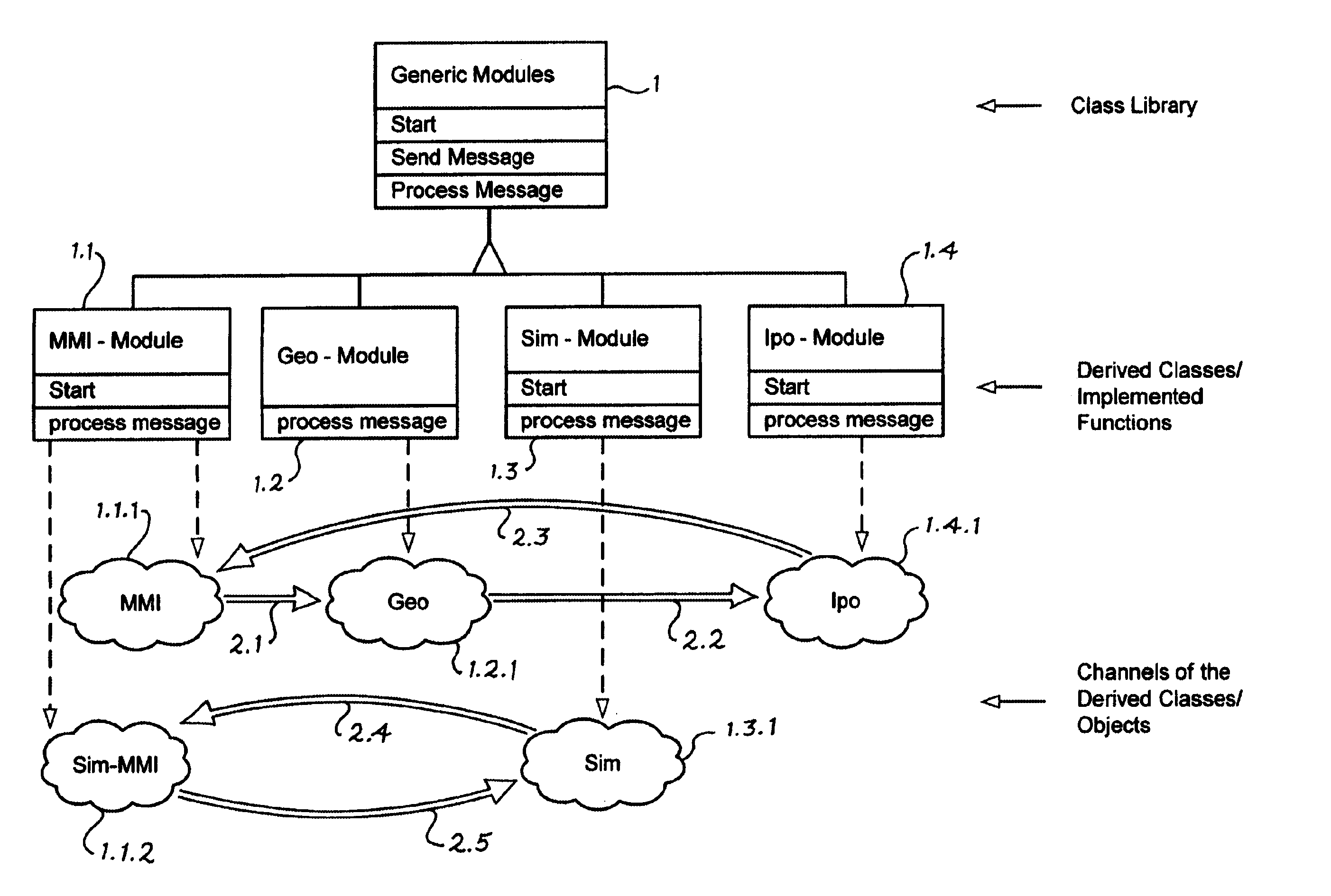
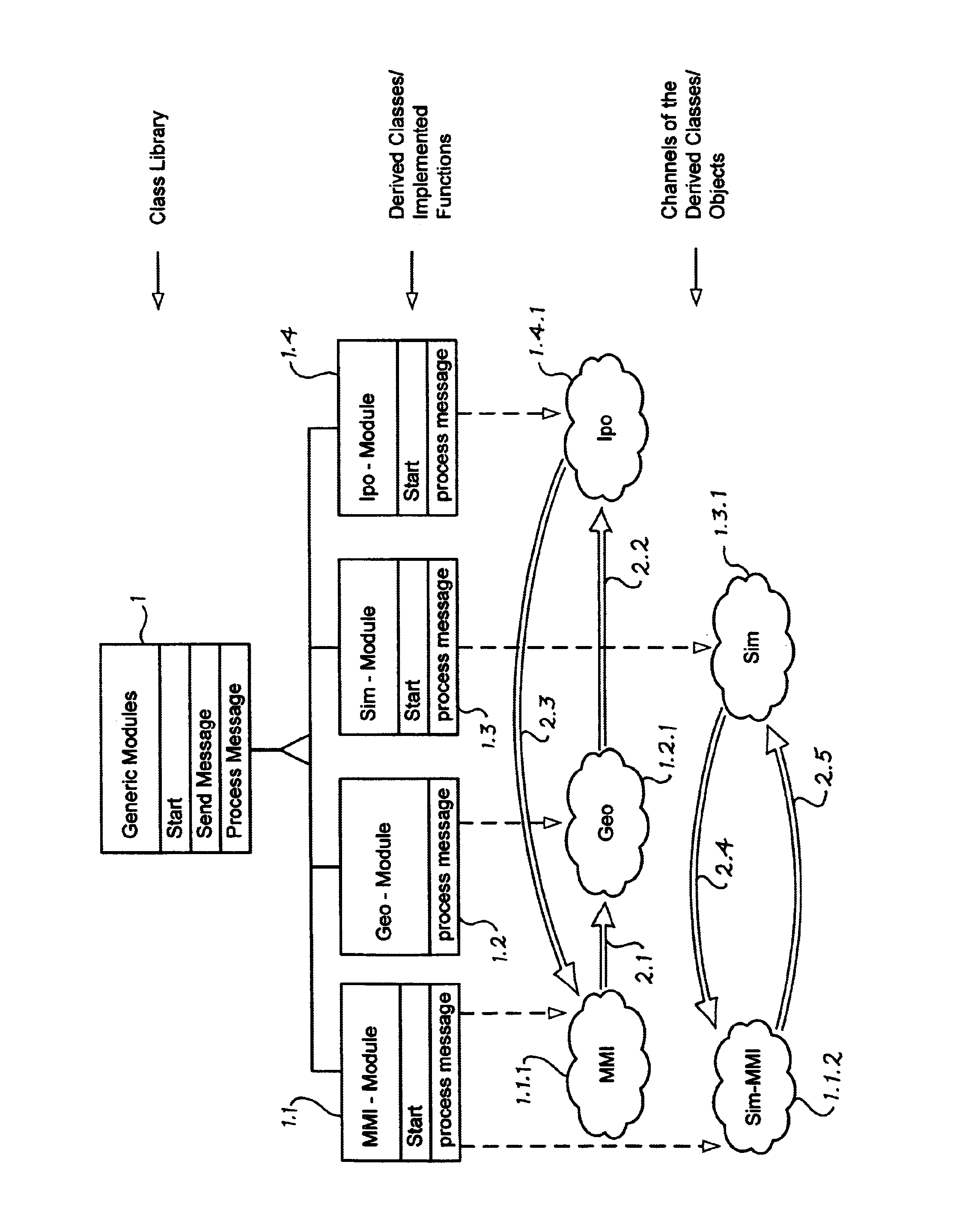
[0022]The control program for a numerical control, shown partially in a graphic form in FIG. 1, has been realized on the basis of a framework, wherein the framework is implemented by at least one class library 1. The essential functions of the control program of a machine tool can be subdivided into functional groups called geometry processing 1.2, interpolator 1.4, man-machine interface 1.1, movement control and a programmable logic controller.

[0023]In accordance with the present invention, a framework class library 1 is provided. The class library 1 contains the software of a generic control for the individual abstracted functionalities and their interaction. In this case only the functional struct...


PUM


Abstract

A control system of a numerically controlled machine tool with a software structure, the control system including a program code of a control program specific to a machine tool and a framework that is independent of an application, wherein the framework is implemented in the form of a class library that has a first set of classes that define a functional structure of the control system. A second set of classes derived from the first set of classes of the framework, wherein the second set of classes contain the program code that is specific to the machine tool and that implements application specific functions of at least one of several functional groups associated with a man-machine interface, geometry processing, an interpolator, movement processing and a programmable logic controller.

Description

[0001]Applicants claim, under 35 U.S.C. §§ 120 and 365, the benefit of priority of the filing date of Oct. 12, 2000 of a Patent Cooperation Treaty patent application, copy attached, Serial Number PCT / EP00 / 10042, filed on the aforementioned date, the entire contents of which are incorporated herein by reference, wherein Patent Cooperation Treaty patent application Serial Number PCT / EP00 / 10042 was not published under PCT Article 21(2) in English.[0002]Applicants claim, under 35 U.S.C. § 119, the benefit of priority of the filing date of Oct. 14, 1999 of a German patent application, copy attached, Serial Number 199 49 558.0, filed on the aforementioned date, the entire contents of which are incorporated herein by reference.BACKGROUND OF THE INVENTION[0003]1. Field of the Invention[0004]The present invention relates to a control system of a numeric machine tool with a reusable software structure.[0005]2. Description of the Related Art[0006]EP 0 524 344 B1 discloses a configurable machin...

Claims


Application Information

Patent Timeline
Patent Type & Authority Patents(United States)
IPC IPC(8): G06F19/00G05B19/4093G05B19/408
CPCG05B19/408Y02P90/02
Inventor RUTKOWSKI, CHRISTIAN
Owner DR JOHANNES HEIDENHAIN GMBH
Why Eureka
Try Eureka