Fixed and variable locking fixation assembly

Inactive Publication Date: 2006-02-21
THEKEN SPINE
View PDF65 Cites 356 Cited by
  • Summary
  • Abstract
  • Description
  • Claims
  • Application Information

AI Technical Summary

Benefits of technology

[0011]Accordingly, the present invention is directed to an implant system suitable for use in small regions such as the cervical spine region, that provides a locking screw having a locking ring located within the head of the screw. The locking ring comprises a lead chamfer or radius on the leading side of the ring that engages a mating lead-in chamfer in the fastener through-hole of the p

Problems solved by technology

This text discusses the fact that severe complications associated with procedures involving the upper cervical spine can be catastrophic, including injuries to the brain stem, spinal cord, or vertebral arteries, not to mention damage to the esophagus.
In procedures involving the cervical spine, additional difficulties are encountered as a direct result of the small space in which the surgeon has to operate.
When the upper cervical area is dissected, surgeons often find it difficult to maneuver because dissection is intimately close to vital neural, vascular, and visceral structures.
As a result, surgeons have little room to operate, and even less room to manually position bone implant structures.
As is well-known, any device implanted into the human body can cause some type of tissue reaction to the implanted foreign material.
Also, in some instances, there are definite anatomic limits to the size of fastener which may be employed for a particular condition.
For these reasons it is sometimes desirable to use the smallest feasible fasteners for fixating bone segments.
Successful use of spinal instrumentation in the anterior cervical spine is particularly difficult since limited space is available due to anatomic constraints.
Such thicknesses increase the risk of damage to the surrounding tissue, esophagus, and other vital anatomical structures.
An additional problem encountered with

Method used


Image

  • Fixed and variable locking fixation assembly
  • Fixed and variable locking fixation assembly
  • Fixed and variable locking fixation assembly

Examples


Embodiment Construction

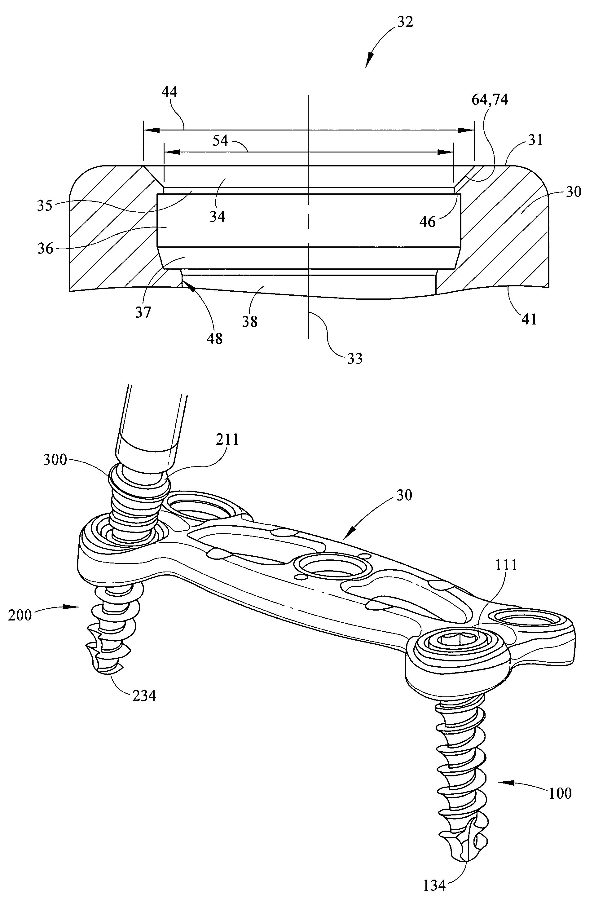
[0039]While the present invention will be described more fully hereinafter with reference to the accompanying drawings, in which particular embodiments and methods are shown, it is to be understood from the outset that persons of ordinary skill in the art may modify the invention herein described while achieving the functions and results of this invention. Accordingly, the descriptions which follow are to be understood as illustrative and exemplary of specific embodiments within the broad scope of the present invention and not as limiting the scope of the invention. Similarly, the present invention is applicable to any structure requiring a fastener, such as a screw 10, that is easily installed in a plate-like member, yet requires relatively great force to remove it from the plate-like member. For the purposes of discussion and ease of understanding, the system of the present invention will be described herein as applicable to a bone fixation plate system wherein an orthopedic plate...


PUM


Abstract

A locking screw assembly is provided which allows installation into a plate-like member using relatively little force, but which requires relatively great force for removal. The fastener has an annular locking ring provided within a groove in the head of the screw to allow the screw to sit within or flush with the anterior surface of the plate. The through-hole in the plate which receives the locking screw comprises an entrance, a collar section, an undercut, and an exit. The locking ring resides within the undercut. The locking ring has a leading surface that is chamfered or radiused and a trailing surface that is flat. The chamfer allows the locking ring to easily be inserted into the through-hole by interacting with a lead chamfer in the entrance. After installation, the flat trailing surface abuts a lip adjoining the collar section and the undercut and prevents the screw from being easily removed from the through-hole.

Description

BACKGROUND OF THE INVENTION[0001]The present invention relates generally to locking fixation assemblies. More specifically, the present invention relates to a fixed and variable locking screw that can be used in bone fixation assemblies.[0002]In the art of orthopedic fixation, it has become common for surgeons to utilize fixation plates for the treatment of spinal disorders including spinal anomalies, spinal injuries, disc problems, and bone problems. Indeed, within the past several years, the use of fixation plates for the treatment of spinal disorders or for fusion of vertebrae has grown considerably, and spinal plates have found increased use and desirability in the cervical spine as well.[0003]As adequately described by Dr. Howard S. An and Dr. Jerome M. Cotler in the publication entitled Spinal Instrumentation, the upper cervical spine can be approached either anteriorly or posteriorly, depending upon the spinal disorder to be treated. This text discusses the fact that severe c...

Claims


Application Information

Patent Timeline
IPC IPC(8): A61B17/56
CPCA61B17/8047A61B17/7059
Inventor NAVARRO, RICHARD R.MADIGAN, DENNIS M.ALBERT, MORTON B.THEKEN, RANDALL R.
Owner THEKEN SPINE
Why Eureka
Try Eureka