
Saw blade for medical applications

a technology for cutting blades and medical devices, applied in the field of cutting blades for medical devices, can solve the problems of high load and wear of bearings, inability to maintain the required cutting precision, and high impact on the cutting accuracy of the blade, so as to achieve the effect of significantly increasing the cutting precision

Inactive Publication Date: 2006-02-21
HAUSMANN THOMAS +1
View PDF11 Cites 62 Cited by
  • Summary
  • Abstract
  • Description
  • Claims
  • Application Information

AI Technical Summary

Benefits of technology

[0011]An object of the invention is to develop a saw blade of the generic type that has much improved dynamic behavior, and, nevertheless, has high static stiffness. Thus, it would become possible to make precise cuts through bones. Furthermore, the durability of the saw will be improved, particularly with regard to its bearings.
[0013]The impressions in the surface of the saw blade influence the ability of the blade to transport or relay vibrations, i.e., they influence the dynamic behavior of the saw blade. In this way, the vibration behavior of the saw blade can be greatly reduced when in operation; while the precision of the cut is increased accordingly.
[0019]Furthermore, dynamic properties are especially improved when the surface impressions are located at equidistant intervals to one another. The distance between two surface impressions can be between 0.5 mm and 10 mm, and preferably between 1 mm and 5 mm.
[0022]The embodiments of the saw blade of the invention leads to the vibrations during sawing being reliably damped at the start of the vibration building-up process. Thus, over the entire frequency range with which the saw blade is excited during the sawing process, the blade does not tend to vibration perpendicular to the blade surface, and the cutting precision is thus significantly increased.

Problems solved by technology

The required precision varies less than a millimeter, and known saw blades engender problems in this respect.
In the resonant area, the vibration amplitude can become so large that in spite of the use of templates, which exactly guide the saw, the required sawing precision cannot be maintained.
The cut becomes inexact which results in the corresponding consequences in surgery.
Another disadvantage is caused by the fact that the saw being used is exposed to high dynamic stress so that its bearings are subject to high loads and wear.
Reducing the thickness of the saw blade does not yield any overall benefit, since the dynamic effect as a result of the reduced mass of the saw blade is less, but deflection of the blade is increased when working forces are applied.

Method used


Image

  • Saw blade for medical applications
  • Saw blade for medical applications
  • Saw blade for medical applications

Examples


Embodiment Construction

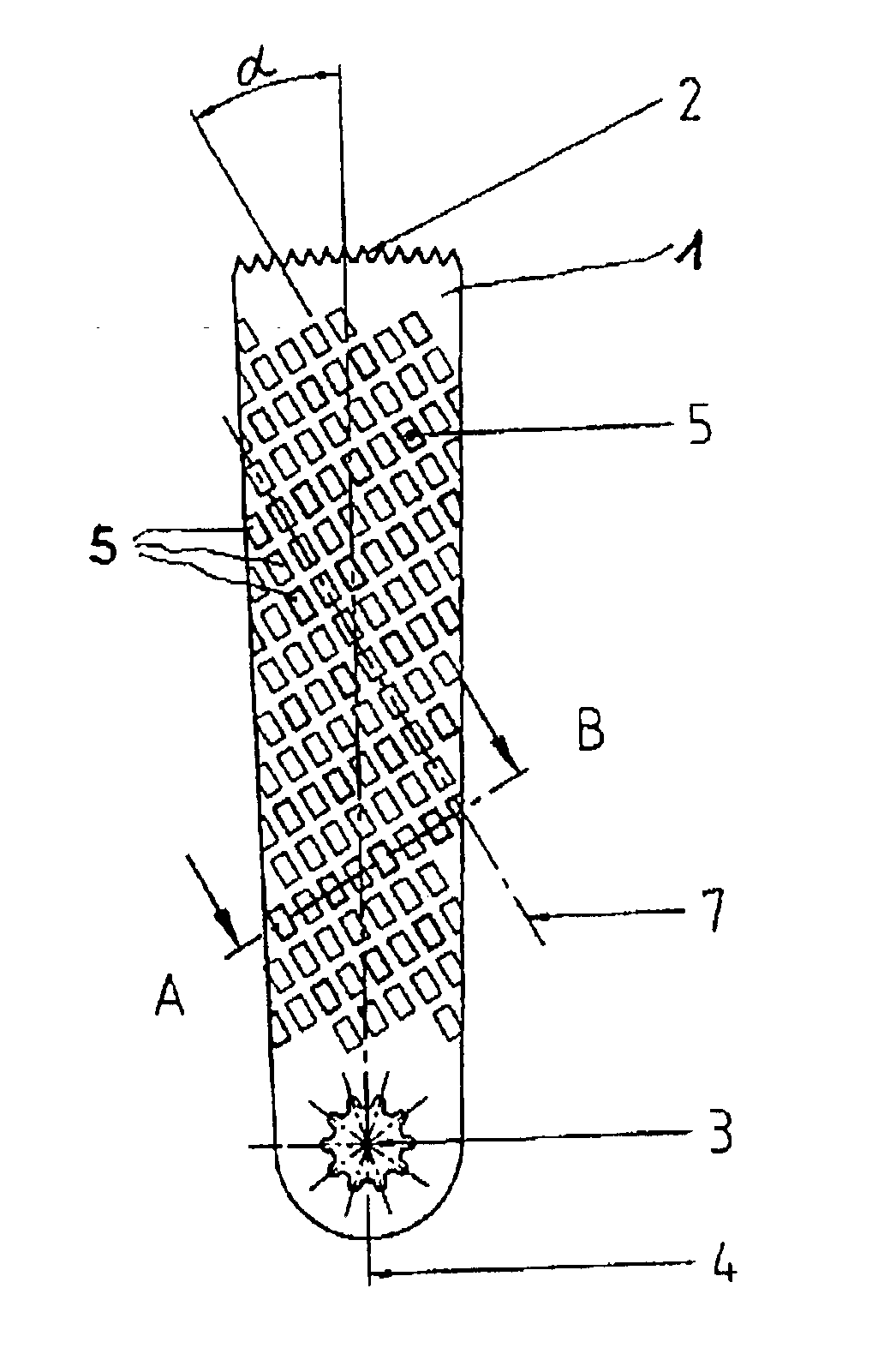
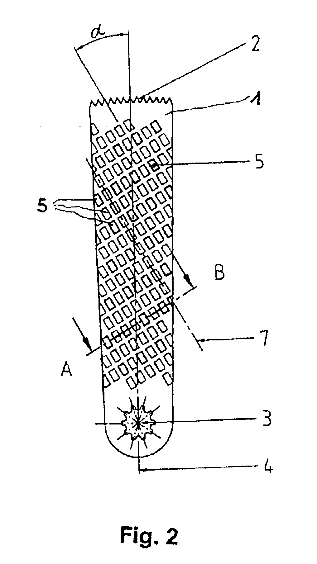
[0030]The saw blade shown in FIG. 2 in an overhead view includes a flat base body of high-alloy chromium steel. The saw blade 1 has a lengthwise axis 4. On one end, the saw blade 1 is provided with a sawtooth profile 2 made for example by a laser cutting process. On the other end, a receiver 3 is machined which has a multitooth profile that interacts with a corresponding counterpiece of the saw (not shown).

[0031]In operation, the saw turns the saw blade 1 around the center point of the receiver 3 in the plane of the flat area surfaces of the blade so that the sawtooth profile 2 is moved back and forth, and thus can cut through bone and other tissue.

[0032]To improve the dynamic behavior, the surface of the saw blade is provided with a host of surface impressions 5. In the embodiment shown in FIG. 2, the impressions 5 are made in the form of small rectangles.

[0033]As can be seen in FIG. 2, the individual rectangles are oriented in a straight line alignment to one another. The rectangl...


PUM

PropertyMeasurementUnit
Tensile strengthaaaaaaaaaa
Angleaaaaaaaaaa
Diameteraaaaaaaaaa

Abstract

A saw blade for medical, in particular surgical, applications having a recess for mounting the saw blade inside a saw which exerts an saw movement, especially an oscillating saw movement, to the saw blade. In order to improve the dynamic behavior of the saw blade, longitudinal flat areas of a surface of the saw blade are provided with a plurality of superficial impressions of a defined contour that are aligned at an angle to the longitudinal axis of the saw blade.

Description

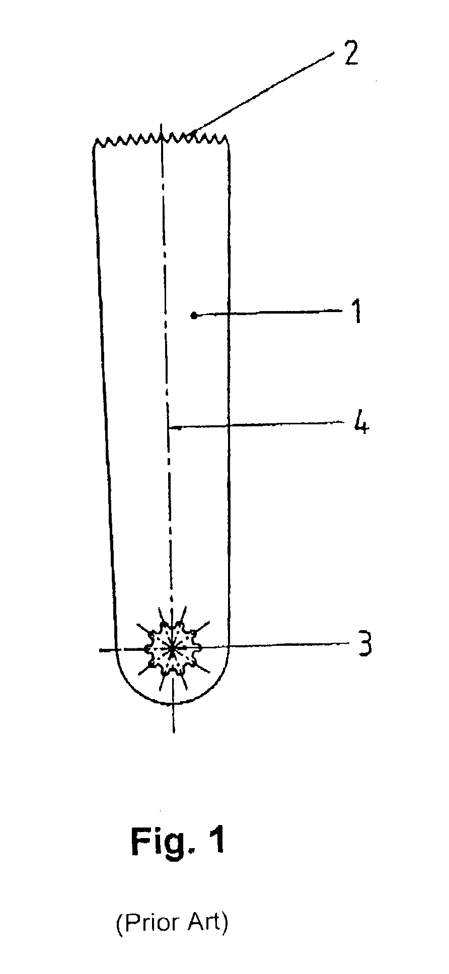
BACKGROUND OF THE INVENTION[0001]1. Field of the Invention[0002]The invention relates to a saw blade for medical, particularly surgical applications, having a receiver for accommodating a saw which applies a sawing motion, especially an oscillating sawing motion, to the saw blade.[0003]2. Discussion of Related Art[0004]Particularly in the area of knee surgery, is it necessary to cut the knee or knee sections and other tissue, such as cartilage or the like, by means of a saw when an artificial knee joint is implanted. To do this, compressed air-driven or electrical saws (often battery-driven devices) are known which have a saw blade as is shown in FIG. 1.[0005]The saw blade (1) is made as a thin sheet and, therefore, has a flat structure. On one end, it has a sawtooth profile (2) which cuts the bone. The saw blade (1) is held in the saw by means of a receiver (3), for example, with a multitooth profile. The saw applies a sawing motion to the saw blade. In this case, the saw turns the...

Claims


Application Information

Patent Timeline
IPC IPC(8): A61B17/14A61B17/32B23D61/02
CPCA61B17/14A61B17/148B23D61/025B23D61/006A61B17/141A61B17/142
Inventor HAUSMANN, THOMASHENDRICH, CHRISTIAN
Owner HAUSMANN THOMAS
Learn More