Stormwater treatment apparatus and method

a treatment apparatus and a technology for stormwater, applied in sedimentation settling tanks, separation processes, filtration separation, etc., can solve the problems of high property values, soil conditions, and the proximity of other building foundations that often preclude the use of conventional, space-intensive stormwater bmp's such as detention ponds, and the effectiveness of these devices for removing suspended solids and oil and grease has been marginal

Inactive Publication Date: 2006-02-21
JENSEN ENTERPRISES
View PDF117 Cites 43 Cited by
  • Summary
  • Abstract
  • Description
  • Claims
  • Application Information

AI Technical Summary

Benefits of technology

[0054]The apparatus advantageously settles particles down to a size of 100 microns and smaller out of suspension in the stormwater by utilizing a unique volume control design. The vault of the present invention is designed to treat a given volume of stormwater runoff, as opposed to a given runoff flow rate as treated in other devices. In so doing, the horizontal flows for the entire volume of water to be treated can be nearly eliminated, such that with a reduced flow rate very small particles may drop out of suspension and collect on the bottom of the vault. This is accomplished through a combination of physical space to capture and hold water to be treated, restriction of flow out of the apparatus at a slower flow rate than flow into the apparatus, and vertically stacked pools of water with reduced or eliminated relative flow velocity.
[0079]A further advantage of vertically stacked pools including a permanent pool is that of maintaining a compact footprint or plan area. By both treating the incoming volume of water and storing sediments in the same plan area more water volume can be treated on a given site.

Problems solved by technology

Space constraints, high property values, soil conditions, and the proximity of other building foundations often preclude the use of conventional, space-intensive stormwater BMP's such as detention ponds.
Vault-type treatment technologies have been widely used for stormwater treatment in urban areas; however, the effectiveness of these devices for removal of suspended solids and oil and grease has been only marginal.
A great weakness of these types of devices has been that large storm events tend to flush out the system, thereby releasing pollutants that were previously removed.
All of these devices are somewhat effective at settling out particles down to a certain size or specific gravity, but none of these devices are effective at removing the very small size range of particles that make up the majority of toxic pollutants in storm water runoff.
However, such systems provide little or no detention capture volume to mitigate the runoff peaks for small or large runoff events.
In other words, these systems function as flow-through devices, resulting in the lack of capture volume and overall poor treatment performance.
Specifically, much of the settleable materials trapped or deposited during more numerous smaller runoff events are agitated and remobilized, and wash out of these devices when larger and more intense runoff events occur.
Because of site-specific limitations, however many desirable features of wet detention ponds are not utilized in real world conditions.

Method used


Image

  • Stormwater treatment apparatus and method
  • Stormwater treatment apparatus and method
  • Stormwater treatment apparatus and method

Examples


Embodiment Construction

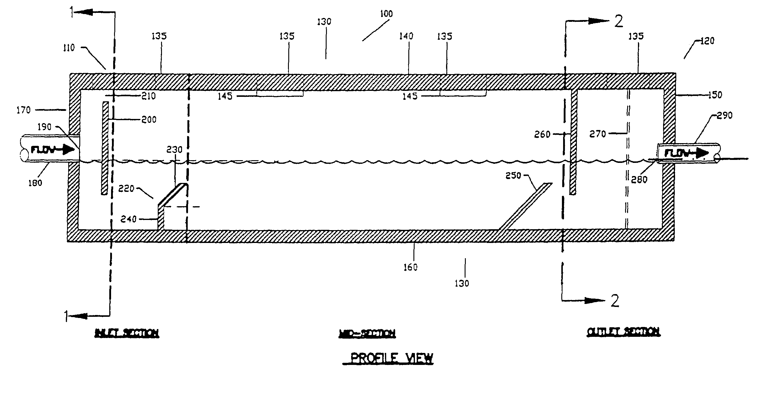
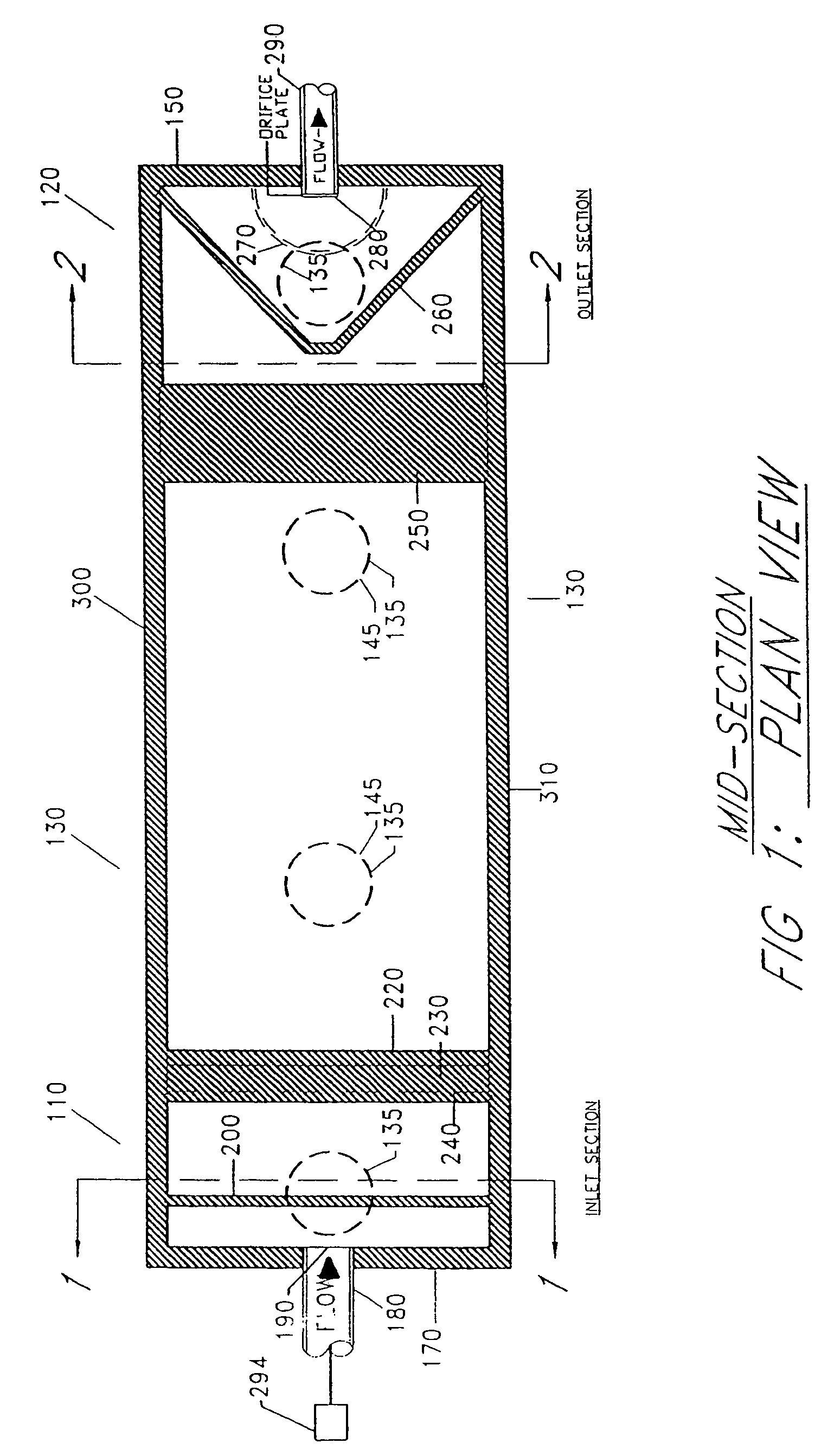
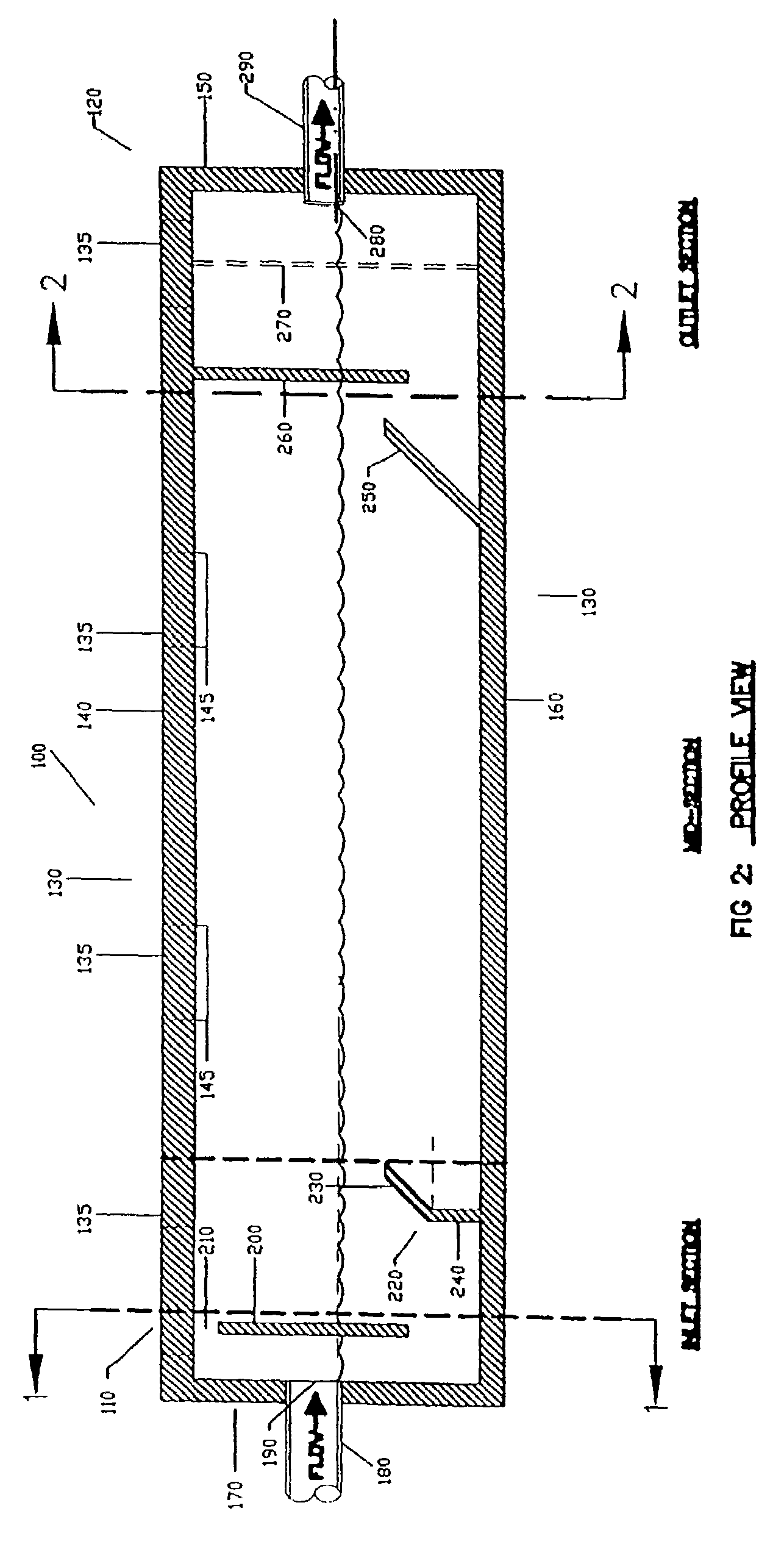
[0093]The drawings illustrate one embodiment of an apparatus 100 for separation of pollutants that are less and more dense than water from stormwater runoff. Referring to FIG. 1 and FIG. 2, the apparatus 100 consists of a top 140, a bottom 160, an inlet end 170, an outlet end 150, a left side 300, and a right side 310 (left and right are relative to the view from the inlet end 170 to the outlet end 150). These sides define a rectangular chamber with an inlet section 110, an outlet section 120, and one or more midsections 130.

[0094]The length of the most basic configuration of the apparatus 100 is desirably at most 20 ft, more desirably at most 18 ft 6 in, and, most preferably, 17 ft 6 in (inside dimension); and the width of the apparatus id desirably at most 10 ft, more desirably at most 8 ft 6 in, and, most preferably, 7 ft 6 in (inside dimension); the height of the apparatus is 6 ft or 8 ft (inside dimensions). Outside dimensions and inside dimensions may vary due to structural st...


PUM


Abstract

A liquid purification and separation apparatus for separation of pollutants in stormwater runoff is disclosed. This apparatus utilizes gravitational separation and tortuosity, resulting from a plurality of baffles both perpendicular to and oblique to the primary water flow direction, to trap substances less-dense and more-dense than water. The apparatus features improved resistance to pollutant remobilization through treatment of water volume rather than flow rates, using vertically stacked water columns of varying depths to settle small particles. An overflow structure diverts excessive liquid without interfering with purification and separation, and can be placed integrally within or external to the apparatus receptacle.

Description

RELATED APPLICATIONS[0001]This application is a divisional of U.S. patent application Ser. No. 10 / 084,837, filed Feb. 26, 2002, now U.S. Pat. No. 6,638,424, and entitled “Stormwater Treatment Apparatus” which is a continuation-in-part of U.S. patent application Ser. No. 09 / 487,097, filed Jan. 19, 2000, now U.S. Pat. No. 6,350,374, and entitled “Stormwater Treatment Apparatus.” Both prior applications are incorporated herein by reference in their entirety.BACKGROUND OF THE INVENTION[0002]1. Field of the Invention[0003]Apparatus for treatment of stormwater runoff through volume-control-based detention and minimization of pollutant remobilization.[0004]2. Description of the Related Art[0005]This invention relates generally to liquid purification and separation and, more specifically, to an apparatus for separation of pollutants in urban stormwater runoff from the runoff water. This apparatus utilizes gravitational separation and tortuosity, resulting from a plurality of baffles both pe...

Claims


Application Information

Patent Timeline
Patent Type & Authority Patents(United States)
IPC IPC(8): B01D21/02B01D17/00B01D21/00E03F5/14
CPCB01D17/00B01D21/00E03F5/14B01D21/307B01D21/02B01D21/0042B01D21/003B01D17/0208B01D17/0211B01D17/0214B01D21/0039B01D2221/12B01D21/0006
Inventor STEVER, R. RUSSELLURBONAS, BEN R.JONES, JONATHAN E.EARLES, ANDREWSARRATT, EDWARD SCOTTSCHNEIDER, ERIC RICHARDPHELPS, STEVEN C.
Owner JENSEN ENTERPRISES
Why Eureka
Try Eureka