
Treated water dispensing system

a technology of dispensing system and water treatment, which is applied in the direction of filtration separation, separation process, instruments, etc., can solve the problems of reducing the efficiency of water purification, so as to prevent contamination by bacteria or other contaminants, increase ultraviolet exposure, and save money

Inactive Publication Date: 2006-02-21
GREENE RALPH G
View PDF3 Cites 25 Cited by
  • Summary
  • Abstract
  • Description
  • Claims
  • Application Information

AI Technical Summary

Benefits of technology

Ensures effective UV disinfection of both room temperature and chilled water, reduces UV lamp cycling, extends bulb life, and provides protection against leaks and contamination, while offering user insights into system performance and cost savings.

Problems solved by technology

The water, however, may be easily contaminated with bacteria by contact with air on the storage and dispensing mechanisms, or merely by sitting stagnant in the reservoir.
The light energy from a UV lamp is germicidal, because UV light penetrates microbial organism's protective membrane layer and photochemically damages the DNA structure, disabling its self-reproducing capability and rendering the cell lifeless.
The typical storage reservoir for water purification units is not usually suitable for effective UV application.
Since UV has a limited effective transmission distance, the physical dimensions of a 4 to 6 gallon storage reservoir have not been suitable for effective UV application.
A very high intensity UV lamp would be required in such cases and this would heat the chilled water thereby reducing the efficiency and effectiveness of the chilling process.
Moreover, UV degrades most plastics, and typically in large reservoirs, floats and switches are constructed of plastic.
It has been observed in U.S. Pat. No. 6,139,726 that the known prior art has not solved any of these problems.
Although U.S. Pat. No. 6,139,726 is a large improvement over the prior art, there still remains a need to reduce the cycling on and off of the UV bulb as well as the “on” time of the bulb as these factors degrade the life of the bulb.
However, even with these improvements, there sometimes exists a need to utilize a larger wattage of UV lamp.

Method used


Image

  • Treated water dispensing system
  • Treated water dispensing system
  • Treated water dispensing system

Examples


Embodiment Construction

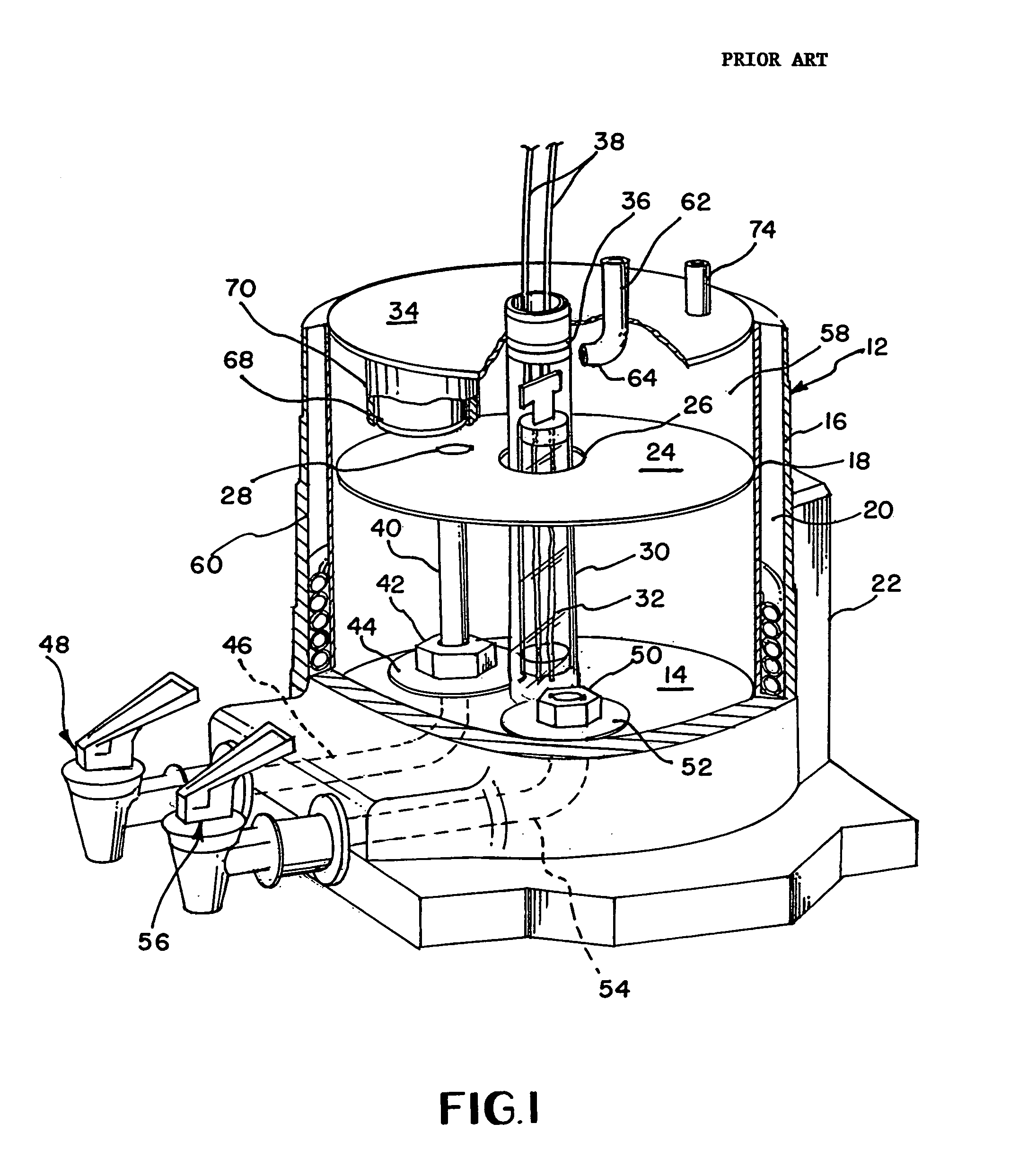
[0031]Referring now to the drawing FIG. 1 illustrates a prior art water dispenser 10. The dispenser 10 includes a housing 12 having a hollow interior including a base 14 and an exterior upstanding wall 16. In at least the lower portion of the housing above the base spaced inwardly from the wall 16 is a second wall 18. Tubing forming cooling coils 20 are received in a coiled condition between the walls 16 and 18, the coils 20 carrying coolant communicating with refrigeration apparatus (not illustrated) mounted within a bulbous portion 22 of the housing 12 preferably externally of the wall 16 for reasons which will hereinafter become clear.

[0032]Fastened to the interior wall 18 within the hollow interior of the dispenser is a baffle plate 24, the baffle plate preferably being constructed from stainless steel and having a substantially central opening 26 and a smaller offset opening 28. Extending downwardly through the opening 26 and having portions disposed both above and below the ba...


PUM

PropertyMeasurementUnit
temperatureaaaaaaaaaa
areaaaaaaaaaaa

Abstract

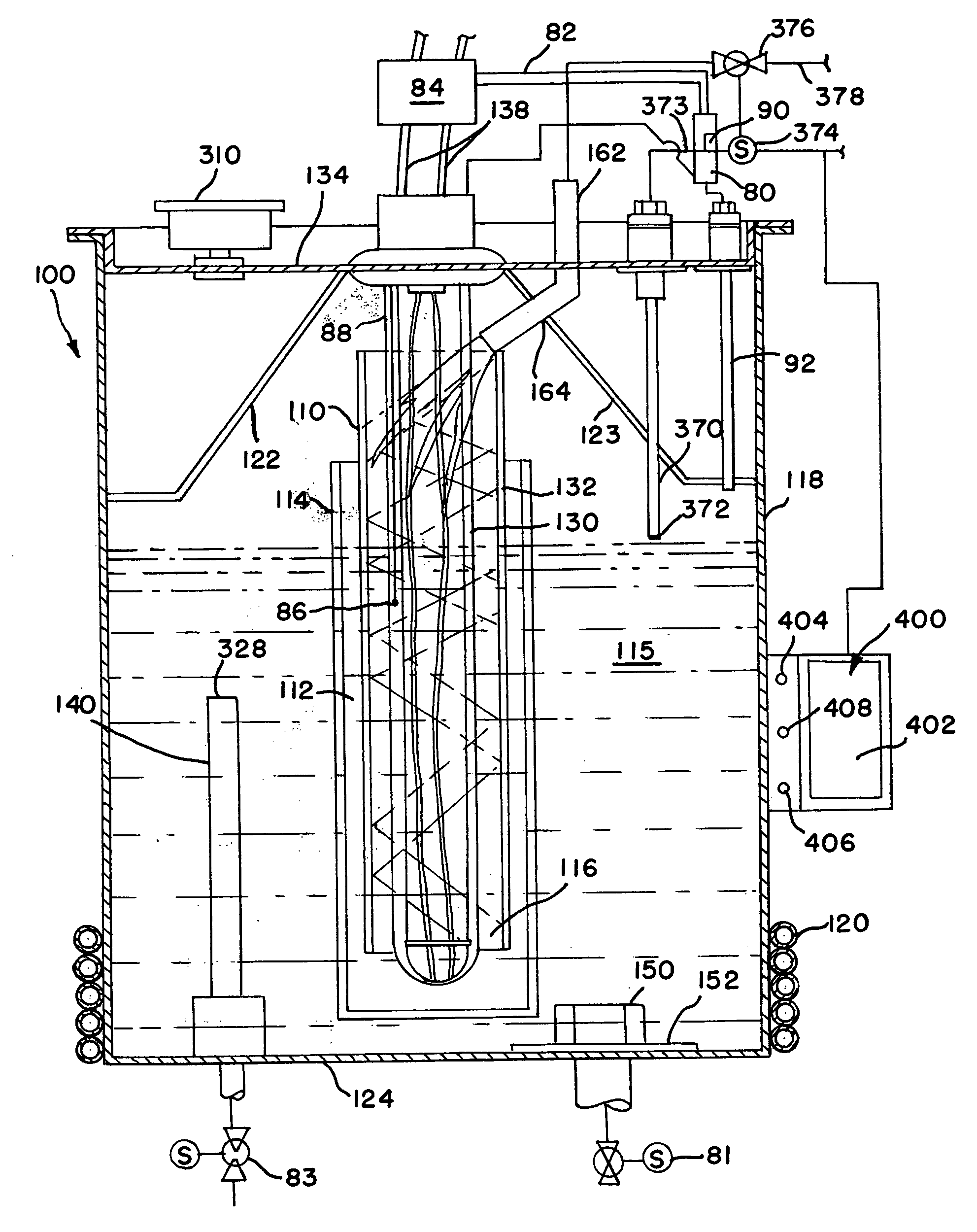
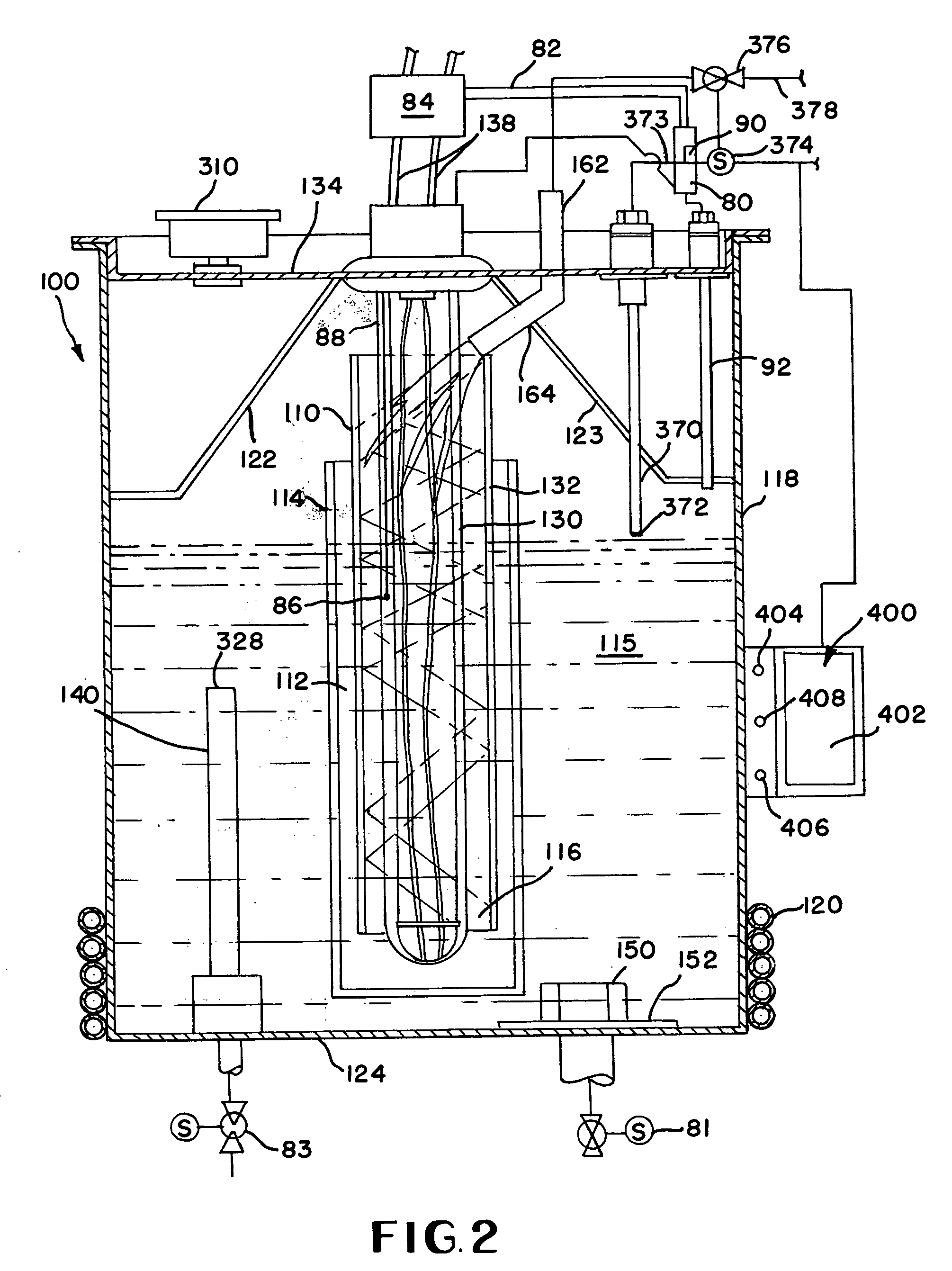
A water treatment tank for use with water purification apparatus including an ultra-violet lamp within an encapsulating sleeve onto which incoming water is directed to provide a thin laminar flow about the bulb. The lower compartment has cooling coils about the walls for cooling the water therein relative to the water in the upper compartment. A surrounding sleeve may be located intermediate the encapsulating sleeve and an outer vessel in the tank. A leak detector is located in the encapsulating sleeve. The leak detector and outer vessel are believed to provide safety to users in the event of internal breakage in the tank. A reflective surface is also utilized to direct UV light into portions of the faucets formerly obscured from UV treatment. The faucets preferably provide self-sanitizing capability and an information center selectively displays time until next service, cost savings over bottled water and information related to the dispenser.

Description

BACKGROUND OF THE INVENTION[0001]Water purification devices which purify at slow rate, such as those which use the distillation and the reverse-osmosis processes, deliver water into a storage tank or reservoir from which the water is dispensed. The same is true in regard to systems which use bottled water and water filter dispensing coolers. The water, however, may be easily contaminated with bacteria by contact with air on the storage and dispensing mechanisms, or merely by sitting stagnant in the reservoir. This is particularly true with bottled water cooler dispensers and those units that are used as replacements for bottled water cooler dispensers since the tanks are non-pressurized, and therefore must be vented to permit water to be dispensed by gravity flow.[0002]A known method for eliminating bacterial contamination is the use of ultra-violet (“UV”) light. The light energy from a UV lamp is germicidal, because UV light penetrates microbial organism's protective membrane layer...

Claims


Application Information

Patent Timeline
Patent Type & Authority Patents(United States)
IPC IPC(8): A61L2/10C02F1/00C02F1/32
CPCC02F1/008C02F1/325A61L2/10C02F2307/06C02F2201/326C02F2201/328C02F2301/022C02F2201/3228
Inventor GREENE, RALPH G.
Owner GREENE RALPH G
Learn More