Collimator optical system and optical information storage device

a technology of optical information storage and collimator, which is applied in the direction of data recording, instruments, mountings, etc., can solve the problems of reduced optical stability and the increase of the switch of laser output, and achieve high-quality recording and reproduction, optically stable performance

Inactive Publication Date: 2006-02-21
FUJITSU LTD
View PDF11 Cites 16 Cited by
  • Summary
  • Abstract
  • Description
  • Claims
  • Application Information

AI Technical Summary

Benefits of technology

[0015]In view of the circumstances, an object of the present invention is to provide a collimator optical system of a simple structure optically stable against both temperature changes and light source output changes and an optical information storage device of which performance is stable against both the temperature changes and light source output changes.

Problems solved by technology

If rendered shorter-wavelength and higher-NA, however, aberrations accompanying a change in ambient temperature and a switch of laser output become larger and optical stability is reduced.

Method used


Image

  • Collimator optical system and optical information storage device
  • Collimator optical system and optical information storage device
  • Collimator optical system and optical information storage device

Examples


first embodiment

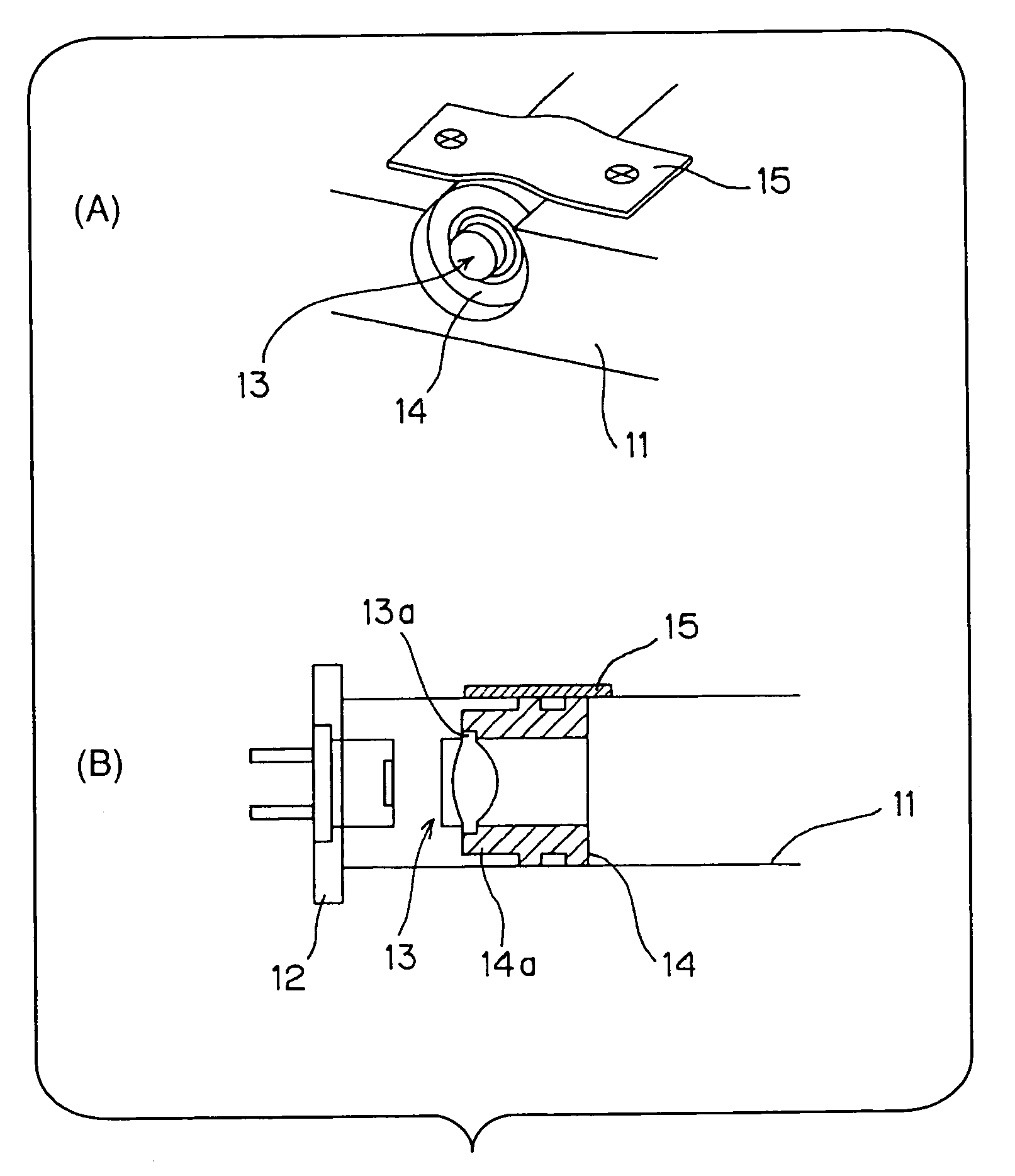
[0097]Part (A) of FIG. 7 is a perspective view and (B) is a sectional view representing the collimator optical system of the present invention.

[0098]The first embodiment shown in FIG. 7 has a base 11 made of aluminum of the fixed optical assembly, the laser diode 12 fixed on the base 11 and emitting blue diffused light of 405 nm, an achromatic lens 13 functioning as the collimator lens that converts the diffused pencils of light emitted by the laser diode 12 to the parallel pencils of light, a lens holder 14 made of aluminum that holds the achromatic lens 13, and a plate spring 15 fixing the lens holder 14 on the base 11.

[0099]The description of the first embodiment will also use the laser diode 12 as the reference of the directions of the members so that the side close to the laser diode 12 will be referred to as the front side and the side far from the laser diode 12 will be referred to as the backside.

[0100]The achromatic lens 13 has a two-group lens structure in which a convex l...

second embodiment

[0105]Part (A) of FIG. 8 is a perspective view and part (B) is a sectional view representing the collimator optical system of the present invention.

[0106]A second embodiment shown in FIG. 8 includes a plastic lens 23 and a lens holder 24 in place of the achromatic lens 13 and lens holder 14 of the first embodiment, and also includes the base 11, laser diode 12 and plate spring 15 as with the first embodiment.

[0107]The description of the second embodiment will also use the laser diode 12 as the reference of the directions of the members so that the side close to the laser diode 12 will be referred to as the front side and the side far from the laser diode 12 will be referred to as the backside.

[0108]The plastic lens 23 has the overhang (edge section) 23a provided on its rim, and the front side of the edge section 23a is bonded to the lens holder 24 in the second embodiment so as to have the plastic lens 23 held by the lens holder 24. The plastic lens 23 has diffraction gratings 23b c...


PUM

PropertyMeasurementUnit
wavelengthaaaaaaaaaa
focal lengthaaaaaaaaaa

Abstract

The present invention is intended, as an object thereof, to improve stability against both temperature changes and light source output changes, and includes an achromatic lens having a composite structure of glass or a plastic lens having a diffraction grating counteracting a focal length change due to a wavelength change of light, where a lens holder is adhered to an opposite side to a light source of an overhang of the achromatic lens made of glass while the lens holder is adhered to a light source side of the overhang of the plastic lens with the diffraction grating.

Description

[0001]This application is a continuing application, filed under 35 U.S.C. §111(a), of International Application PCT / JP02 / 12512, filed Nov. 29, 2002.TECHNICAL FIELD[0002]The present invention relates to a collimator optical system that converts diffused pencils of light to parallel pencils of light and an optical information storage device that reads information from an information recording medium by means of light.BACKGROUND ART[0003]Conventionally, an optical disk device that reads and records information by means of light by using an optical disk such as a CD, a CD-ROM, a CD-R, a DVD, a PD, an MO or an MD as an information recording medium is known as a kind of an optical information storage device. Importance is attached to such an optical disk device because the optical disks are characterized by replaceability, large capacity, small size and lightweight. A small and low-cost laser diode is generally used as a light source of the optical information storage device represented b...

Claims


Application Information

Patent Timeline
Patent Type & Authority Patents(United States)
IPC IPC(8): G02B7/02G02B27/30G02B5/18G11B7/12G11B7/123G11B7/135G11B7/1353G11B7/1376G11B7/1392
CPCG11B7/123G11B7/13922G11B7/1376G11B7/1353
Inventor UNO, KAZUSHIHAMAGUCHI, SHINGO
Owner FUJITSU LTD
Why Eureka
Try Eureka