Coupling mechanism for an optical transceiver housing

a technology of optical transceiver and coupling mechanism, which is applied in the direction of electrical apparatus casing/cabinet/drawer, electrical apparatus construction details, instruments, etc., can solve the problems of reducing the value of providing low-cost and reliable optical transceivers, potential damage, and low manufacturing cost of optical transceiver modules. , to achieve the effect of substantially reducing or eliminating the interference of the cover or the electro-optical assembly

Active Publication Date: 2006-02-21
LUMENTUM OPERATIONS LLC
View PDF7 Cites 20 Cited by
  • Summary
  • Abstract
  • Description
  • Claims
  • Application Information

AI Technical Summary

Benefits of technology

[0014]Further consistent with achieving the foregoing aspects, the present invention makes provisions for a method of assembling components of an optical transceiver. The method comprises the steps of: providing a carrier; providing a cover joinable together with the carrier to define an enclosure therebetween; providing an electro-optical subassembly within the enclosure and supported by the carrier, providing a coupling mechanism on one

Problems solved by technology

However, because these optical transceiver modules are relatively expensive to manufacture and relatively fragile in construction, it is important to avoid damaging them during the assembly process.
Typically, during optical transceiver module assembly a heat sink cover is manually placed over and on a carrier base that supports a printed circuit board having expensive and compactly arranged electro-optical components of the optical transceiver module mounted thereon.
Unles

Method used


Image

  • Coupling mechanism for an optical transceiver housing
  • Coupling mechanism for an optical transceiver housing
  • Coupling mechanism for an optical transceiver housing

Examples


Embodiment Construction

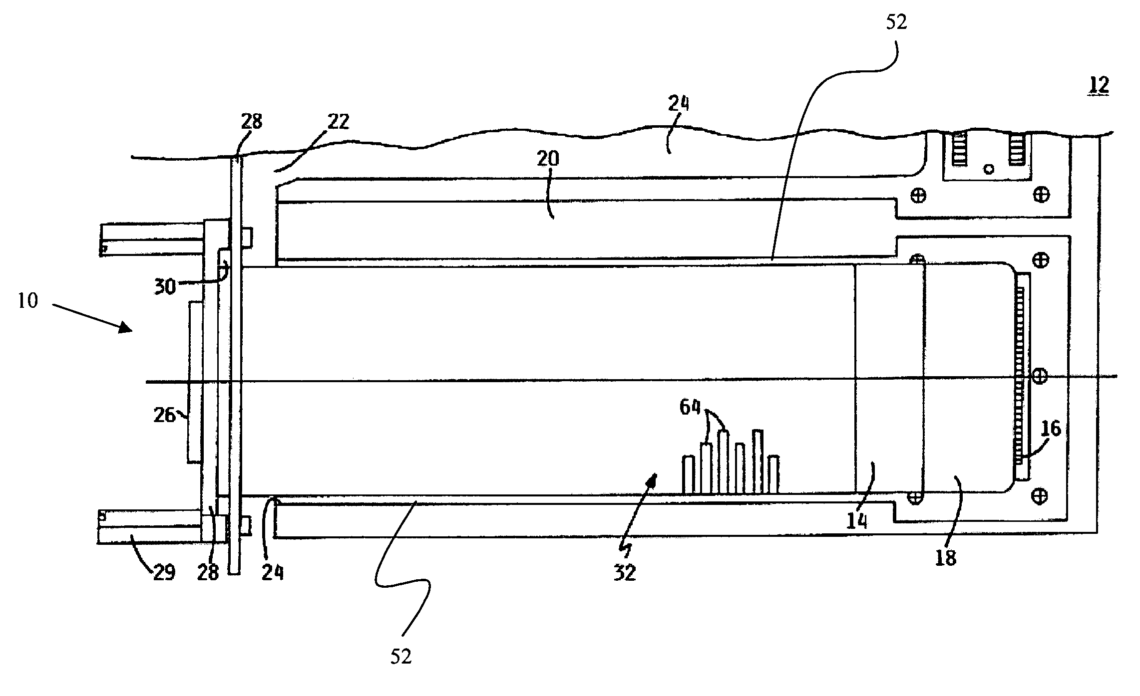
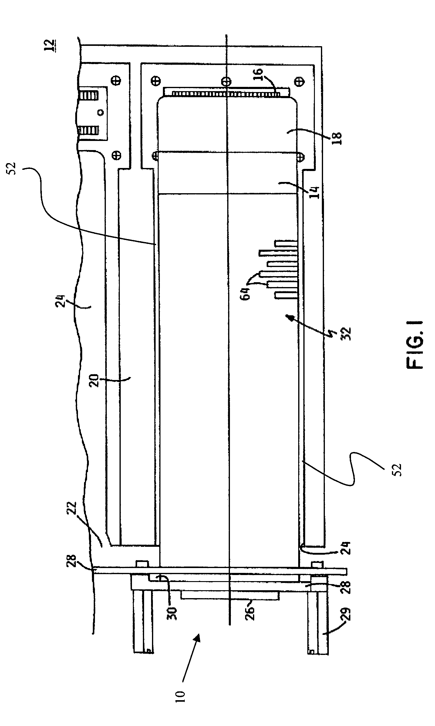
[0021]FIGS. 1–5 illustrate one preferred embodiment of an optical transceiver module 10 made according to the principles of the present invention and illustrated as being mounted in a host data transfer system 12.

[0022]With reference to FIG. 1, a first or proximal end portion 14 of the optical transceiver module 10 is to be coupled directly to a card edge connector 16 that is covered in a metal shroud 18 and is otherwise connected to a network adapter card 20 housed within the confined space 22 formed by the host data transfer system 12. The host data transfer system 12 can be a mid-range computer system commercially available from International Business Machines Corporation, Armonk, N.Y. Other types of data transfer or communication systems are contemplated for use with the optical transceiver module 10 of the present invention, such as input / output devices or other peripheral devices. The optical transceiver module 10 is otherwise slideably received within one of a plurality of el...


PUM


Abstract

An optical transceiver providing a carrier; a cover couplable to a portion of the carrier to define a transceiver enclosure; and, an electro-optical assembly supported in the enclosure is provided. A coupling mechanism and cooperating structure are particularly adapted to define pivoting motion of the cover relative to the carrier, whereby interference of the cover and the electro-optical assembly is avoided. Methods of assembling the transceiver components are present.

Description

BACKGROUND OF THE INVENTION[0001]The present invention relates generally to a laser-based data communication interconnect apparatus for effecting optical data transfer and, more particularly, to a compact optical transceiver apparatus having an improved housing with an improved coupling mechanism and method of assembly.[0002]Optical transceiver modules are known in the data transmission field for effecting bidirectional data transmission, whereby electrical signals are converted to optical signals and vice versa. In operation, a transmitter unit of the optical transceiver module functions to convert incoming electrical signals to corresponding optical signals. Conversely, incoming optical signals are converted by the optical transceiver module's receiving unit into corresponding electrical data signals. These units are typically mounted on a circuit host card that is normally associated with a host computer, input / output device, switch, or other peripheral device.[0003]In general, t...

Claims


Application Information

Patent Timeline
IPC IPC(8): H04B10/00H05K7/14
CPCH05K7/1428
Inventor BRANCH, SCOTT MICHAELHANLEY, MICHAEL FRANCIS
Owner LUMENTUM OPERATIONS LLC
Why Eureka
Try Eureka