
Method for deriving the benchmark program for estimating the maximum power consumed in a microprocessor

a microprocessor and benchmark program technology, applied in the field of microprocessor design, can solve the problems of complex power estimation of a processor at the architectural level, inability to provide implementation details, and high dependence on implementation, so as to achieve the effect of reducing the complexity of the power estimation process and reducing the complexity of the process

Inactive Publication Date: 2006-02-21
HEWLETT-PACKARD ENTERPRISE DEV LP
View PDF1 Cites 19 Cited by
  • Summary
  • Abstract
  • Description
  • Claims
  • Application Information

AI Technical Summary

Benefits of technology

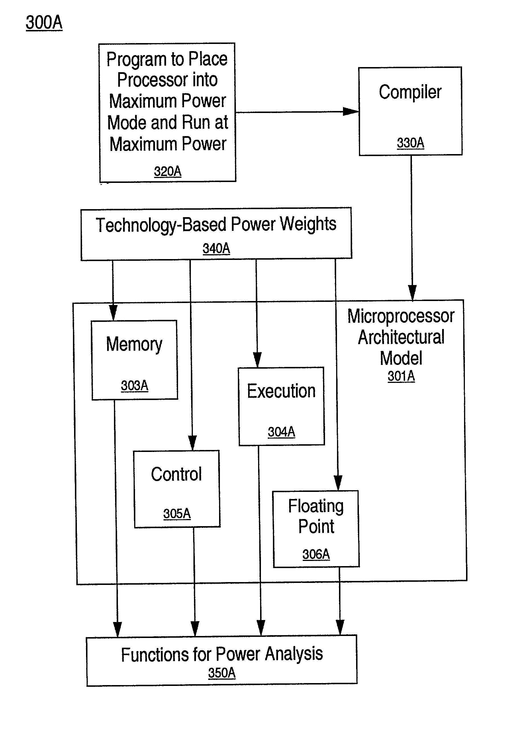
[0020]In one embodiment, the present invention provides a method achieving the foregoing accomplishments, applicable to any microprocessor architecture, other integrated circuit architecture, or system, including computer systems, under design. In the present embodiment, maximum power efficiency of PC, workstation, and other processors, other integrated circuits (IC), including application specific ICs, and systems is separated from the architectural component and the technology component of processor power estimation and analysis. This approach provides complete freedom to perform power-aware architectural experiments using behavioral level simulations for any processor, without interference or slow-down due to the implementation technology parameters, permitting significant analysis of any design.

Problems solved by technology

Power estimation for a processor at the architectural level is a complex problem.
At this stage of processor design, conceptual ideas are being evaluated, and implementation details are not yet available.
Power consumption, on the other hand, is very much dependent on implementation.

Method used


Image

  • Method for deriving the benchmark program for estimating the maximum power consumed in a microprocessor
  • Method for deriving the benchmark program for estimating the maximum power consumed in a microprocessor
  • Method for deriving the benchmark program for estimating the maximum power consumed in a microprocessor

Examples


Embodiment Construction

[0033]In the following detailed description of the present invention, numerous specific details are set forth in order to provide a thorough understanding of the present invention. However, it will be recognized by one skilled in the art that the present invention may be practiced without these specific details or with equivalents thereof. In other instances, well known methods, procedures, components, and circuits have not been described in detail as not to unnecessarily obscure aspects of the present invention.

[0034]Notation and Nomenclature

[0035]Some portions of the detailed descriptions, which follow, are presented in terms of procedures, steps, logic blocks, processing, and other symbolic representations of operations on data bits that can be performed by computer systems. These descriptions and representations are used by those skilled in the data processing arts to most effectively convey the substance of their work to others skilled in the art. A procedure, computer executed...


PUM


Abstract

In one embodiment, for an electronic architecture with a functional constitution performing a number of functions characterized by separate stages performing subfunctions, a method of deriving a benchmark program for estimating the maximum power consumption by modeling a functional model of the architecture, compiling the benchmark program into a corresponding instruction stream, valuating power weights for each stage of each function of each constituent, inserting the power weights, running the model in a maximum power consumption mode, and summarizing power consumption. In one embodiment, the benchmark program is applied by specifying a design analysis to be performed, selecting a function, designating a stages performing that function, removing a set of instruction set architecture instructions corresponding the designated stage, emulating the constituent subfunction corresponding to the stages designated stage, and summarizing. In one embodiment, the model is written in SystemC. In one embodiment, a compiler used is a PERL script.

Description

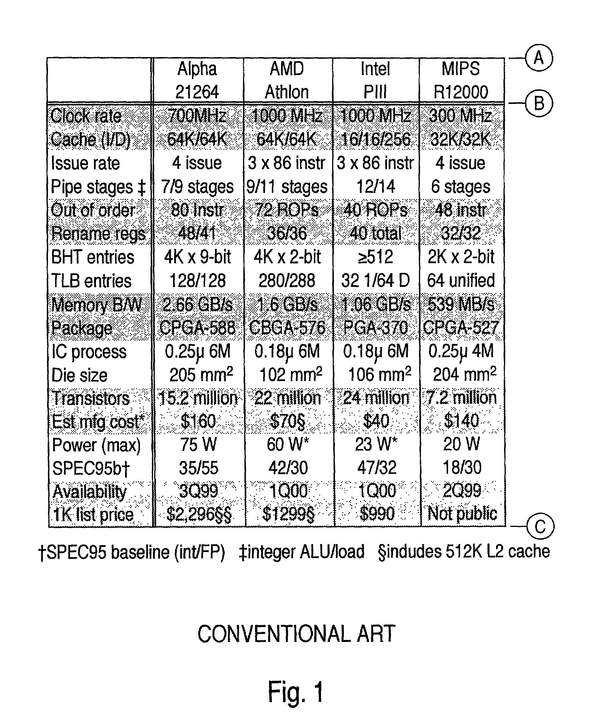
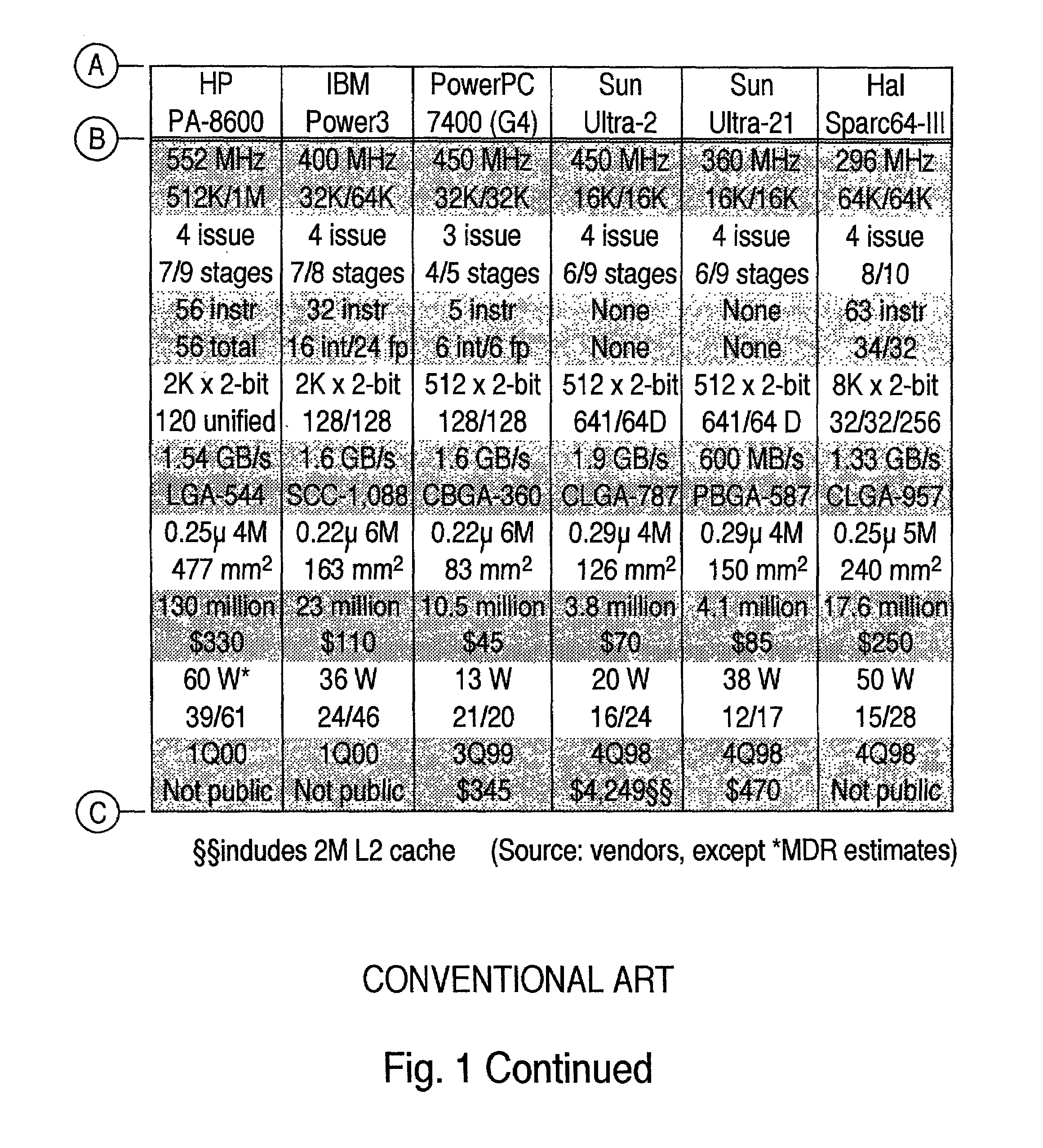
BACKGROUND OF THE INVENTION[0001]1. Field of the Invention[0002]The present invention relates to the field of microprocessor design. Specifically, the present invention relates to a method for analyzing the power expenditure of microprocessor designs at the architectural level, including accurate estimation of maximum power consumption.[0003]2. Related Art[0004]Performance requirements have pushed microprocessor complexity to millions of devices per chip, and clock rates into the GHz range. Consequent microprocessor power consumption is outpacing gains from advances and scaling in silicon technologies, and benefits of reduced power supply voltages. Thus, power consumption is a major issue in microprocessor design, and reducing power consumption without adversely affecting performance is a major challenge. Conventional Art FIG. 1 illustrates this situation for contemporary personal computer and workstation processor architectures.[0005]The power consumption issue affects almost every...

Claims


Application Information

Patent Timeline
Patent Type & Authority Patents(United States)
IPC IPC(8): G06F17/50G06F1/26G06F1/32
CPCG06F1/32G06F1/26
Inventor VENKITAKRISHNAN, PADMANABHA
Owner HEWLETT-PACKARD ENTERPRISE DEV LP
Learn More