High temperature splash plate for temperature reduction by optical reflection and process for manufacturing

a technology of optical reflection and high temperature, applied in the direction of machines/engines, efficient propulsion technologies, lighting and heating apparatus, etc., can solve the problems of undesired radiation directed to the side, increase the life of the splash plate, and increase the operating temperature of the splash plate. , the effect of thermal degradation of the splash plate is not as rapid

Inactive Publication Date: 2006-02-28
GENERAL ELECTRIC CO
View PDF20 Cites 16 Cited by
  • Summary
  • Abstract
  • Description
  • Claims
  • Application Information

AI Technical Summary

Benefits of technology

[0012]An advantage of the present invention is that the radiation from the combustion process is reflected from the portion of the splash plate coated with the high temperature reflective material away from the splash plate, typically back into the gas flow path. This radiative heat, rather than being absorbed by the splash plate, is absorbed by the fluid in the gas flow path and carried back into portions of the engine that currently operate at cooler temperatures. The result is that the splash plate does not become as hot, so that it can operate at a cooler temperature in a given design. Alternatively, the combustor design can be modified to permit higher combustor temperatures without increasing the operating temperature of the splash plate. The reflective coating increases the life of the splash plate, as the thermal degradation of the splash plate is not as rapid.
[0013]Another advantage of the present invention is that the fluid stream will be heated to a higher temperature as the reflected radiation from the splash plate is absorbed by the fluid and carried from the combustor portion of the engine into the turbine portion of the engine. This increased temperature translates into increased engine efficiency, as the available energy in the fluid stream is greater.
[0014]Still another advantage of the present invention is that, since the engine can be operated at an even higher temperature than currently experienced, the current invention allows for an engine to operate at greater efficiency.

Problems solved by technology

Even a slight variation in the surface of the coated splash plate can cause some of the radiation to be directed in an undesired direction, such as onto an adjacent combustor component rather than being directed toward the turbine nozzle at the downstream end of the combustor.

Method used


Image

  • High temperature splash plate for temperature reduction by optical reflection and process for manufacturing
  • High temperature splash plate for temperature reduction by optical reflection and process for manufacturing
  • High temperature splash plate for temperature reduction by optical reflection and process for manufacturing

Examples


Embodiment Construction

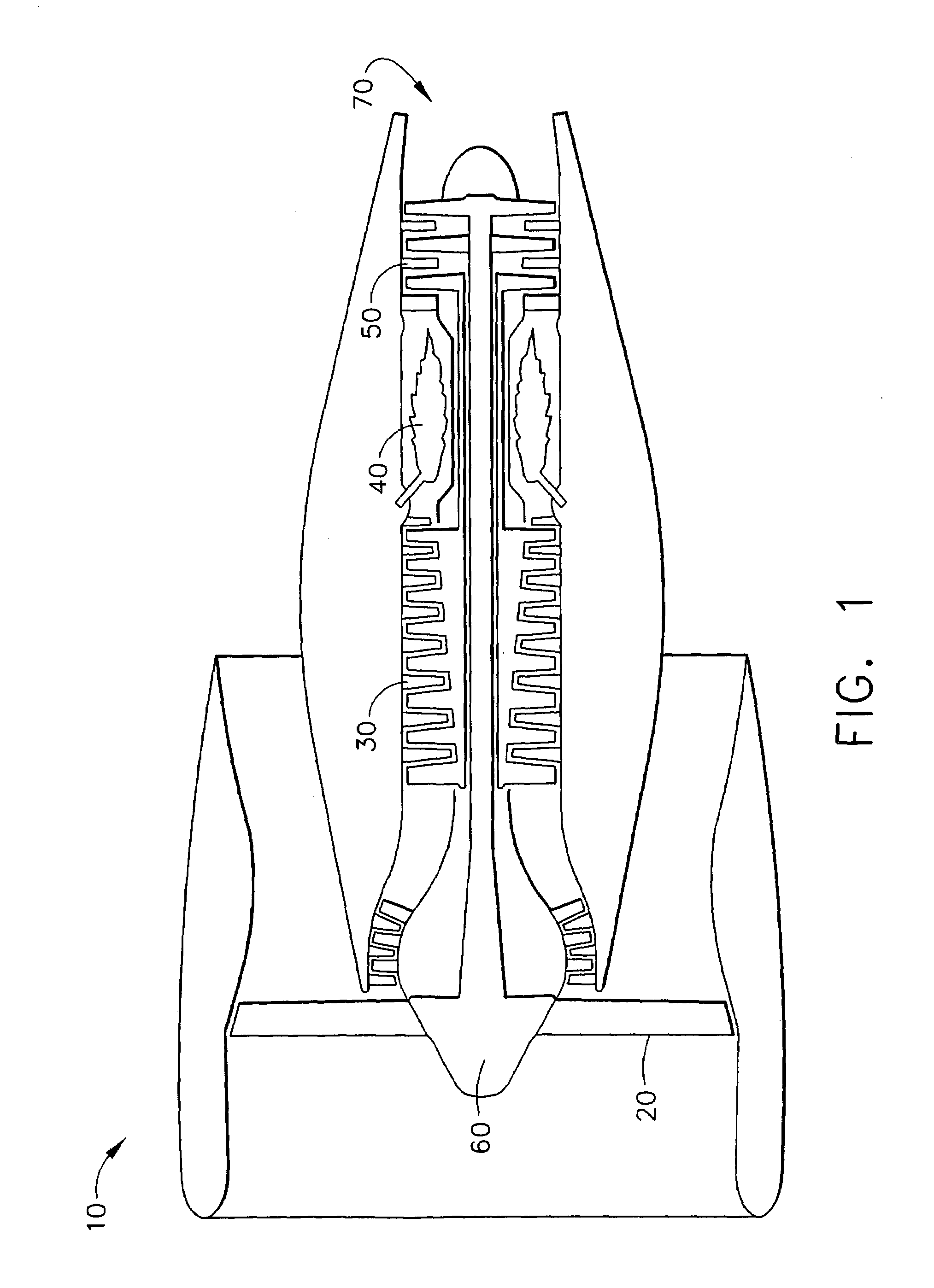
[0024]FIG. 1 is a cross section of a typical high bypass ratio turbofan engine 10. A simple description of the operation of such an engine follows. Air enters engine 10 through fan 20 and passes into compressor section 30, which includes a plurality of compressor stages. The compressed air is passed into the back portion of the engine. Some of the air is passed into the combustors 40, only one of which is illustrated, while some air is used for other purposes such as downstream cooling of components and cabin pressure. In the combustors 40, compressed air is mixed with fuel and ignited. The hot gases of combustion are moved downstream to the turbine section 50, which includes a plurality of turbine stages. Energy is extracted by the turbine section to drive the compressor stages 30 and fan 20 via the engine core 60. Hot gases moving beyond the turbine section 50 exit the exhaust portion 70 of engine 10, providing thrust which propels an aircraft forward.

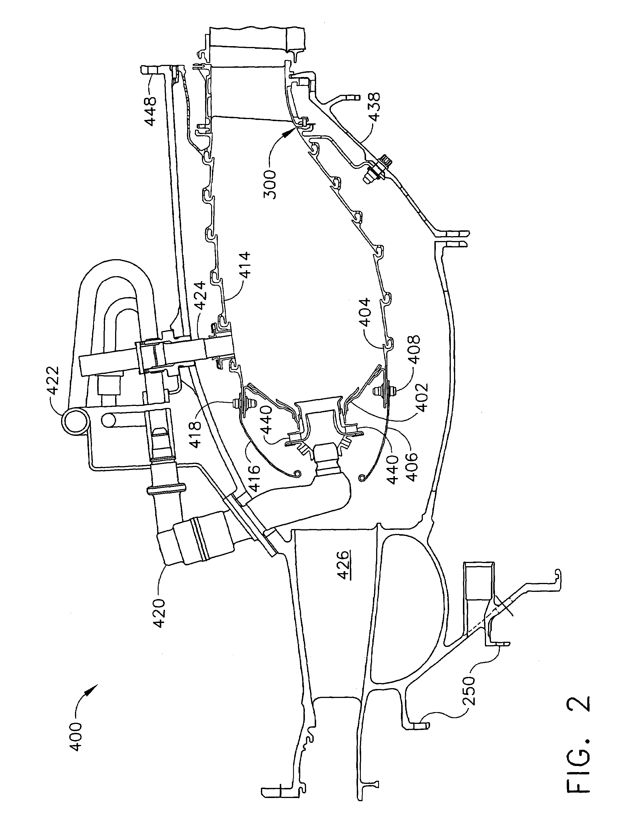
[0025]FIG. 2 depicts a typica...


PUM

PropertyMeasurementUnit
temperatureaaaaaaaaaa
temperaturesaaaaaaaaaa

Abstract

A high temperature splash plate for use in the combustor of a gas turbine engine that also is a specular optical reflector. A thin layer of a high temperature reflector is applied to the surface of the splash plate of the component that forms a boundary for hot combustion gases. The component typically includes a thermal barrier coating overlying the high temperature metallic component that permits the component to operate at elevated temperatures. The thermal barrier coating must be polished in order to provide a surface that can suitably reflect the radiation into the gas flow path. A thin layer of the high temperature reflector then is applied over the polished thermal barrier coating by a process that can adequately adhere the reflector to the polished surface without increasing the roughness of the surface. The surface reflects radiation in the direction of the turbine back into the hot gas flow path. The reflected radiation is not focused onto any other hardware component. The design of the splash plate is such that the radiation is not directed to an adjacent component, which only serves to increase the temperature of the wall of the component.

Description

CROSS-REFERENCE TO RELATED APPLICATIONS[0001]This Application is related to application Ser. No. 10 / 335,647, filed contemporaneously with this Application on Dec. 31, 2002, entitled “IMPROVED HIGH TEMPERATURE CENTERBODY FOR TEMPERATURE REDUCTION BY OPTICAL REFLECTION AND PROCESS FOR MANUFACTURING” assigned to the assignee of the present invention and which is incorporated herein by reference, to application Ser. No. 10 / 335,486, filed contemporaneously with this Application on Dec. 31, 2002, entitled “HIGH TEMPERATURE TURBINE NOZZLE FOR TEMPERATURE REDUCTION BY OPTICAL REFLECTION AND PROCESS FOR MANUFACTURING” assigned to the assignee of the present invention and which is incorporated herein by reference, and to application Ser. No. 10 / 335,442, filed contemporaneously with this Application on Dec. 31, 2002, entitled “IMPROVED HIGH TEMPERATURE COMBUSTOR WALL FOR TEMPERATURE REDUCTION BY OPTICAL REFLECTION AND PROCESS FOR MANUFACTURING” assigned to the assignee of the present invention...

Claims


Application Information

Patent Timeline
Patent Type & Authority Patents(United States)
IPC IPC(8): F23M5/00F01D5/28C23C30/00F01D25/08F02C7/00F02C7/24F23R3/00F23R3/10F23R3/42
CPCF01D25/08F23R3/002F23R3/10F23M2900/05004Y10T428/12542Y02T50/67Y02T50/672Y02T50/675Y02T50/60
Inventor ACKERMANN, JOHN F.ARSZMAN, PAUL V.NAGARAJ, BANGALORE A.YOUNG, CRAIG D.JUSTIS, NICOLE
Owner GENERAL ELECTRIC CO
Why Eureka
Try Eureka