

Fiberizing bushings and methods of using
a technology of fiberizing bushings and fibers, which is applied in the direction of manufacturing tools, lighting and heating equipment, furniture, etc., can solve the problems of insufficient power distribution to the corners of the end wall and tip, affecting the cooling effect of the terminal ear, and cold corners, so as to achieve the effect of increasing the cross sectional area
- Summary
- Abstract
- Description
- Claims
- Application Information
AI Technical Summary
Benefits of technology
Problems solved by technology
Method used
Image

Examples
example 1
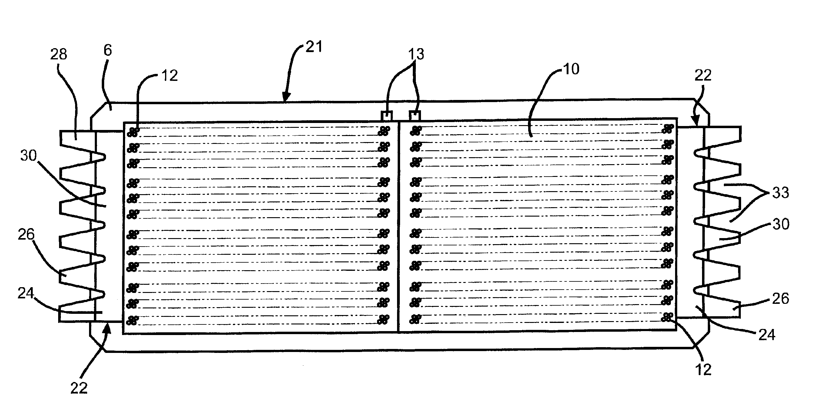
[0040]One preferred bushing was like bushing 21 of FIGS. 3-5. It was fabricated using conventional precious metal alloy forming and welding techniques using an alloy of about 78 percent platinum and about 22 percent rhodium. The bushing was sized in a conventional manner to have about 2580 nozzles or tips. The orifice plate 10 had a thickness of about 1.5 mm and the thickness of the endwalls 8 had a thickness of about 1.4 mm.
[0041]The ear 22, welded onto the exterior of each endwall 8 of the bushing 2 is shown enlarged in FIG. 3A. In this Example the ear 22 was made up of the first part 24 that was about 2.54 mm thick and a second part 26 which was also about 2.54 mm thick. The length of the second part 26 is about 28.6 mm long. The reference marks 32 are stamped into the sides 27 of the second part 26 and spaced apart about 3.175 mm. The second part 26 of the ear 22 has five V-shaped notches 33 in the unattached end with the open end of the V at the unattached end. The enclosed ang...
example 2
[0049]Another preferred bushing 38, made in accordance with FIGS. 6, 6A and 7, was fabricated using conventional precious metal alloy forming and welding techniques using the same alloy as used in Example 1. The bushing 38 was sized in a conventional manner to have about 4030 nozzles or tips 12. The orifice plate 42 had a thickness of about 1.5 mm and the endwalls 40 had a thickness of about 1.4 mm.
[0050]One ear 44 was welded onto the exterior of each endwall 40 of the bushing 38 as shown enlarged in FIG. 7. In this Example the ear 44 was made up of the first portion 50 that was about 2.54 mm thick and the second portion 52 that was also about 2.54 mm thick. The length of the second portion 26 was about 28.6 mm long. The reference marks 54 are stamped into the sides 53 of the second portion 52 and spaced apart about 3.175 mm. The enclosed angle of each V shaped notch 58 is preferably about 30 degrees, but the enclosed angles of all of the V shaped notches 58 need not be identical. T...
PUM
| Property | Measurement | Unit |
|---|---|---|
| included angle | aaaaa | aaaaa |
| included angle | aaaaa | aaaaa |
| included angle | aaaaa | aaaaa |
Abstract
Description
Claims
Application Information