
Method and system for locally sealing a vacuum microcavity, methods and systems for monitoring and controlling pressure and method and system for trimming resonant frequency of a microstructure therein

a vacuum microcavity and local sealing technology, applied in the direction of fluid tightness measurement, semiconductor/solid-state device testing/measurement, instruments, etc., can solve the problems of lack of standardization in wafer-level mems device packaging, complicated already challenging packaging task, and high cost of packaging. , to achieve the effect of reducing the resonance frequency of the microstructur

Inactive Publication Date: 2006-02-28
RGT UNIV OF MICHIGAN
View PDF6 Cites 30 Cited by
  • Summary
  • Abstract
  • Description
  • Claims
  • Application Information

AI Technical Summary

Benefits of technology

[0045]Still further in carrying out the above objects and other objects of the present invention, a method for trimming resonant frequency of a microstructure located within a vacuum microcavity is provided. The method includes locally depositing material onto the microstructure to increase mass of the microstructure whereby resonant frequency of the microstructure is decreased.
[0048]Further in carrying out the above objects and other objects of the present invention, a system is provided for trimming resonant frequency of a microstructure located within a vacuum microcavity. The system includes a power supply and means for transferring power from the power supply to the microstructure so that the microstructure converts the transferred power to a controlled amount of heat over a period of time sufficient to getter material within the microcavity onto the microstructure whereby resonant frequency of the microstructure is decreased.

Problems solved by technology

Packaging is one of the most challenging and costly processes in the IC and sensor industry.
Despite the enormous efforts and technological advances in this area during recent years, IC packaging remains a bottleneck for IC commercialization.
With moving components, the already challenging packaging task is complicated further for MEMS devices.
Thus far, packaging methods reported in the literature are application specific, and there is a lack of standardization in wafer-level MEMS device packaging.
Furthermore, high, unpredictable, residual pressures inside the cavity and vacuum degradation over time are major obstacles in packaging high-performance MEMS devices such as high-quality factor resonators and absolute pressure sensors.
For example, a prior art absolute pressure sensor is capable of resolving pressure changes of 25 mTorr and can be packaged at wafer level; however, it has much lower absolute sensitivity due to the variable pressures in the reference cavity.

Method used


Image

  • Method and system for locally sealing a vacuum microcavity, methods and systems for monitoring and controlling pressure and method and system for trimming resonant frequency of a microstructure therein
  • Method and system for locally sealing a vacuum microcavity, methods and systems for monitoring and controlling pressure and method and system for trimming resonant frequency of a microstructure therein
  • Method and system for locally sealing a vacuum microcavity, methods and systems for monitoring and controlling pressure and method and system for trimming resonant frequency of a microstructure therein

Examples


Embodiment Construction

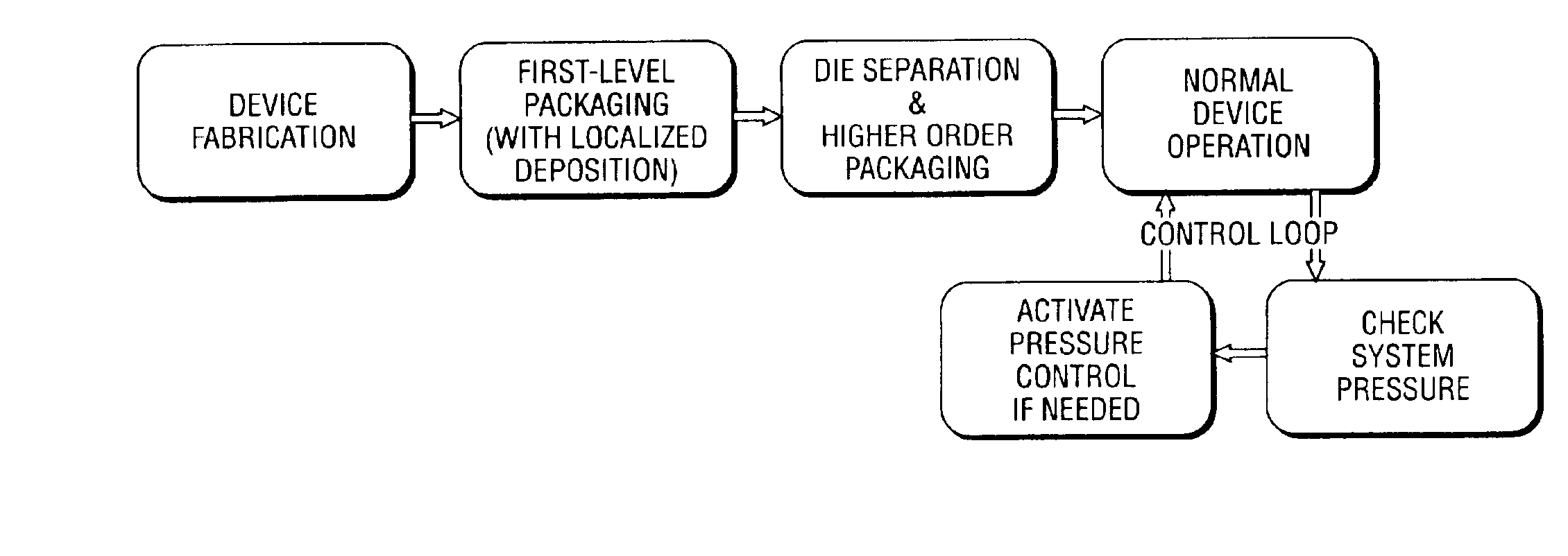
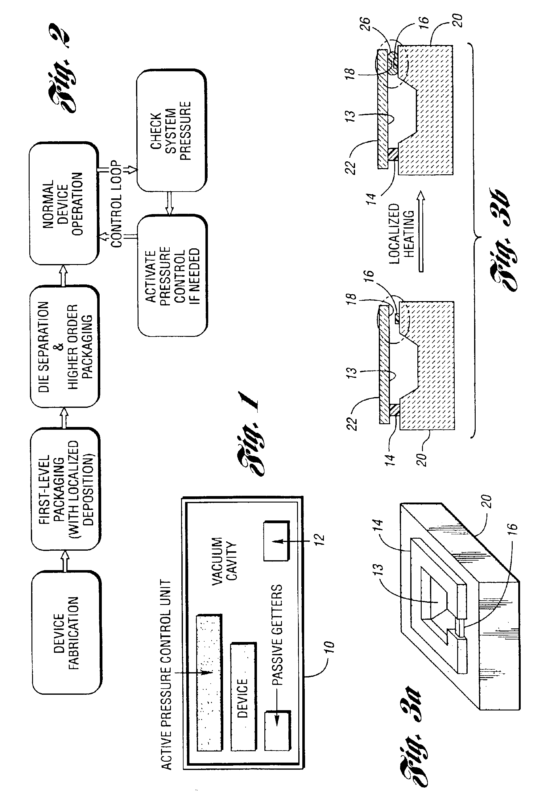
[0059]In general, a post-packaging pressure control scheme integrated with a wafer-level packaging technique is described to address the problems associated with the prior art. The post-packaging pressure control scheme offers a closed-loop, in-chamber pressure monitoring and active pressure control capability to the packaged cavity. This scheme is designed to minimize vacuum degradation in the packaged vacuum microcavity over time, hence improving device performance and lifetime. The wafer-level packaging technique, which is fully compatible with various device fabrication methods (including bulk-micromachining, surface-micromachining, and dissolved wafer process), can be applied to many existing high-performance MEMS devices. This packaging technique is designed to eliminate the high, and unpredictable residual pressures by providing a low and consistent base pressure inside the vacuum microcavity.

Post-Packaging Pressure Control Scheme

[0060]The general approach of this system is t...


PUM

PropertyMeasurementUnit
Pressureaaaaaaaaaa

Abstract

A method and system for locally sealing a vacuum microcavity, methods and systems for monitoring and controlling pressure in the microcavity and method and system for trimming resonant frequency of a microstructure in the microcavity are provided. The microcavity has an initial base pressure therein after the microcavity is locally sealed at an access passageway. The monitoring and control methods include measuring pressure in the microcavity and providing a signal when the pressure exceeds a maximum desired level. The control method also includes reducing the pressure in the microcavity to a pressure at or below the maximum desired level in response to the signal to compensate for vacuum degradation within the vacuum microcavity.

Description

CROSS-REFERENCE TO RELATED APPLICATION[0001]This application claims the benefit of U.S. provisional application Ser. No. 60 / 336,292, filed Oct. 25, 2001.STATEMENT REGARDING FEDERALLY SPONSORED RESEARCH OR DEVELOPMENT[0002]This invention was made with government support under DARPA Grant No. F30602-98-2-0227. The Government has certain rights in the invention.BACKGROUND OF THE INVENTION[0003]1. Field of the Invention[0004]This invention relates to methods and systems for locally sealing a vacuum microcavity, methods and systems for monitoring and controlling pressure and methods and systems for trimming resonant frequency of a microstructure therein.[0005]2. Background Art[0006]Packaging is one of the most challenging and costly processes in the IC and sensor industry. Despite the enormous efforts and technological advances in this area during recent years, IC packaging remains a bottleneck for IC commercialization. With moving components, the already challenging packaging task is co...

Claims


Application Information

Patent Timeline
IPC IPC(8): G01M3/00H01L21/00H01L21/66B81B7/00B81C1/00G01L19/12G01L27/00
CPCB81B7/0038B81B7/0077B81C1/00357G01L19/12H01L22/20G01L27/007B81C2201/019B81C2203/0109B81C2203/0145H01L2924/0002H01L2924/014H01L2924/00Y10T137/0396
Inventor CHANG-CHIEN, PATTY P. L.WISE, KENSALL D.
Owner RGT UNIV OF MICHIGAN
Learn More