Damage resistant and tolerant optical materials

a technology of optical materials and damage resistance, applied in the field of optical elements, can solve the problems of optically induced damage of optically limiting devices, damage to optically limiting devices inside the focal region, and damage to thermomechanical components in the surrounding matrix or host, etc., to achieve maximum performance, prolong shelf life, and increase durability

Inactive Publication Date: 2006-02-28
THE UNITED STATES OF AMERICA AS REPRESETNED BY THE SEC OF THE AIR FORCE
View PDF4 Cites 0 Cited by
  • Summary
  • Abstract
  • Description
  • Claims
  • Application Information

AI Technical Summary

Benefits of technology

[0019]It is an advantage of the present invention that it has ability to form and preserve a dopant concentration distribution not possible in liquids.
[0020]It is another advantage of the present invention that it resists agglomeration of particulate dopants, thus providing longer shelf life and more durability against environmental extremes than liquid, solvent-based optical elements.
[0021]It is a further advantage of the present invention that it allows both the placement of appropriate dopants and the gradient mechanical properties of a host matrix material to be optimized for maximum performance.
[0022]It is a still further advantage of the present invention that it is safer than liquid optical elements where a glass cell may fracture with a resultant spill of hazardous solvents.
[0023]These and other objects, features and advantages of the present invention will become apparent as the description of certain representative embodiments proceeds.SUMMARY OF THE INVENTION
[0024]In accordance with the foregoing principles and objects of the present invention, various example embodiments of a novel optical element are described. The unique discovery of the present invention is that combining gradient mechanical properties with an optimizable geometrical placement of dopants inside a host matrix results in an efficient, optimizable and highly damage resistant and tolerant optical element. For an optical limiter example embodiment, the dopants are absorbing species or other light limiting dopants. For a solid state dye laser example embodiment, the dopant is a lasing or gain media. The viscoelastic properties of the host matrix material can be controlled by controlling crosslink density of a crosslinked polymer which, in the optical limiter example embodiment, combined with geometrical placement of absorbing species (generally a greater concentration of absorbing species in regions of softer matrix material), makes an optical limiter having a very high laser damage threshold.

Problems solved by technology

Such optimized optical limiters, however, are subject to optically induced damage inside that focal region.
Thermomechanical damage occurs by conversion of laser energy to heat at the site of an absorbing inclusion.
The rapid heating process at the inclusion causes a thermomechanical fracture to occur in the surrounding matrix or host.
The resulting small fracture site is a source for scattering and results in an irreversible damage site.
Unfortunately, the susceptibility of these plastic-based optical elements to damage reduces the range over which this type of solid limiter may be used.
A primary disadvantage of liquid limiters is that their performance cannot be optimized by control of the geometrical placement of absorbing species since liquids cannot preserve a concentration distribution.
Liquids are also subject to leaking and other types of failures.
Unfortunately, despite the high damage resistance of some rigid host matrix materials, their operational range as provided through damage resistance is still limited.
Further, they exhibit little damage tolerance.
Damage resistance can only be increased to some level and then irreversible permanent damage will occur.
Unfortunately, solid state dye lasers using polymer host materials are severely limited in power output by low damage thresholds.

Method used


Image

  • Damage resistant and tolerant optical materials
  • Damage resistant and tolerant optical materials
  • Damage resistant and tolerant optical materials

Examples


Embodiment Construction

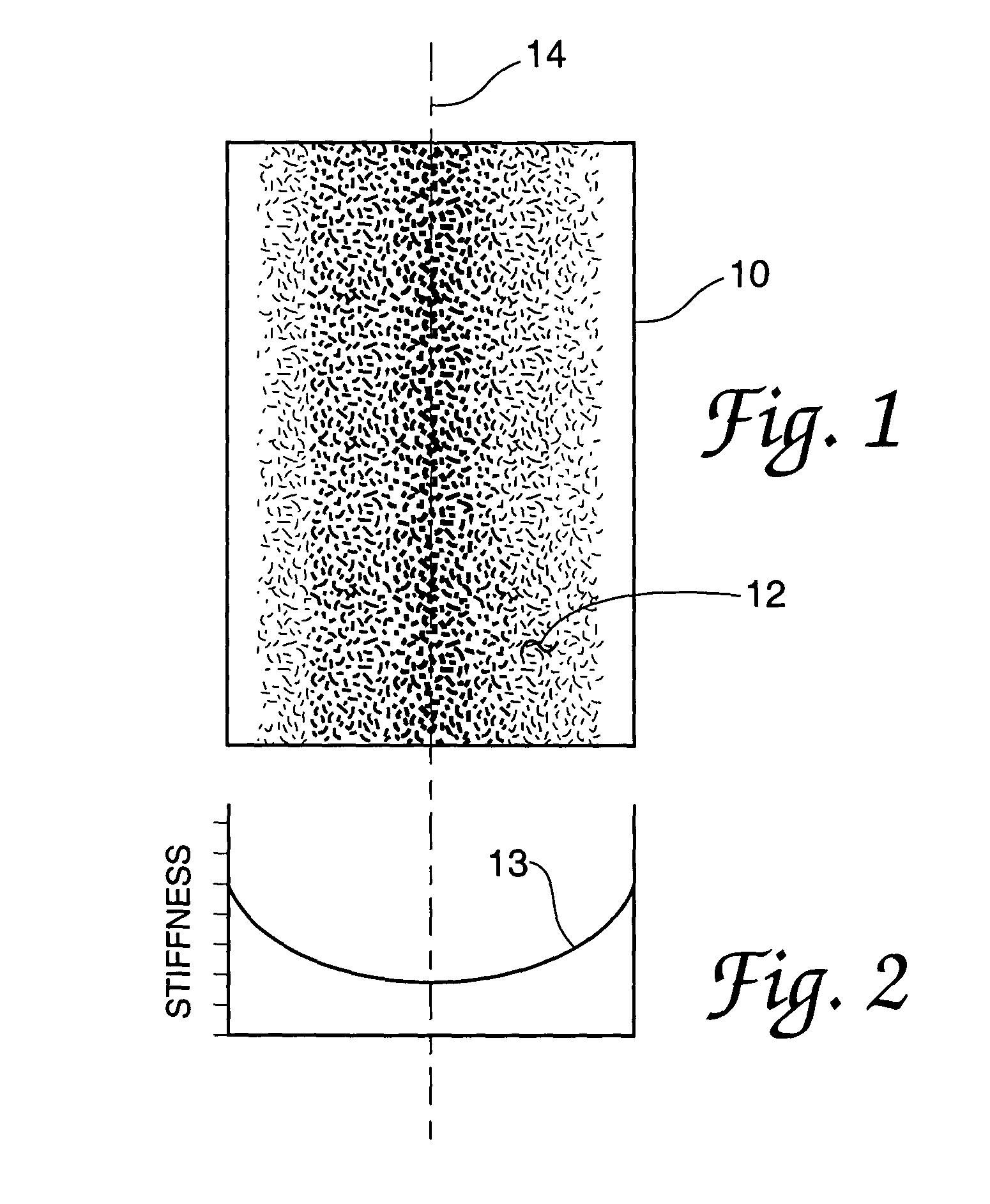
[0036]Referring now to FIG. 1 of the drawings, there is shown a schematic representation of a crosslinked polymer-based optical limiter 10 example embodiment of the present invention showing a distributive doping of a dopant 12. Optical limiter 10 takes the best properties of solid and liquid limiters and combines them into an improved optical element. Replacing a prior art solid or liquid host matrix with a soft crosslinked polymer or similar material does this. The softness of the crosslinked polymer, made in this example embodiment by using a low crosslink density crosslinked polymer, enables the chemical structure to withstand, and possibly dissipate, any thermally-induced mechanical stress which would otherwise cause a fracture at a heated inclusion site.

[0037]The viscoelastic, or mechanical, properties of the crosslinked polymer host material, that is, how soft or stiff the crosslinked polymer, is determined by crosslink density. Crosslink density can be controlled by carefull...


PUM

PropertyMeasurementUnit
Concentrationaaaaaaaaaa
Electrical resistanceaaaaaaaaaa
Stiffnessaaaaaaaaaa

Abstract

A new damage resistant and tolerant optical element is disclosed. Prior art solid or liquid host matrices are replaced by a soft crosslinked polymer or similar host material. The viscoelastic properties of the matrix host material are controlled during formation so that there are regions of different softness, of stiffness, within the matrix, to form a stiffness gradient. Preferably, the matrix will be softest at a preselected focal plane where maximum electromagnetic radiation or energy output may be expected. The host matrix is doped with an appropriate dopant having a concentration distribution, preferably such that the concentration of dopant is highest in the region where the host matrix material is most soft. Two important disclosed example embodiments are an optical limiter and a solid state dye laser.

Description

CROSS-REFERENCE TO RELATED APPLICATIONS[0001]This application is a continuation from U.S. patent application Ser. No. 09 / 874,619, filed Jun. 5, 2001, now U.S. Pat. No. 6,620,863, a continuation-in-part from U.S. patent application Ser. No. 09 / 323,535, filed Jun. 1, 1999, now abandoned, and a continuation-in-part from U.S. patent application Ser. No. 09 / 058,126, filed Apr. 10, 1998, now abandoned, all of which are incorporated by reference into this description.RIGHTS OF THE GOVERNMENT[0002]The invention described herein may be manufactured and used by or for the Government of the United States for all governmental purposes without the payment of any royalty.BACKGROUND OF THE INVENTION[0003]The present invention relates generally to optical elements, and more specifically to optical elements having high damage resistance and tolerance.[0004]An example optical element requiring high damage resistance and tolerance is an optical limiter. Optical limiters are generally transparent optic...

Claims


Application Information

Patent Timeline
IPC IPC(8): B32B5/14B32B27/38C08K5/56C08L63/00G02B5/02C08G59/40C08K5/00
CPCB32B27/38C08G59/40C08K5/0041C08K5/0091C08L63/00Y10T428/31511Y10T428/31515
Inventor MCLEAN, DANIEL G.DEROSA, MICHAEL E.BRANDELIK, DONNA M.CAMPBELL, ANGELA L.BRANT, MARK C.
Owner THE UNITED STATES OF AMERICA AS REPRESETNED BY THE SEC OF THE AIR FORCE
Why Eureka
Try Eureka