Piecewise uniform conduction-like flow channels and method therefor

a flow channel and conduction-like technology, applied in flow mixers, electrolysis, diaphragms, etc., can solve the problems of non-uniform fluid flow, unintended and undesirable hydrodynamic dispersion and stagnation, non-uniform fluid flow persists, etc., to improve the performance of microchannel systems, improve the effect of microchannel system performance, and eliminate the effect of dispersion produced by junctions

Inactive Publication Date: 2006-02-28
SANDIA NAT LAB
View PDF10 Cites 10 Cited by
  • Summary
  • Abstract
  • Description
  • Claims
  • Application Information

AI Technical Summary

Benefits of technology

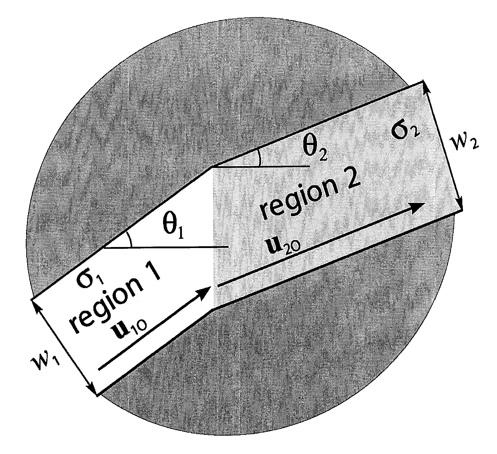
[0008]The present invention improves the performance of microchannel systems by changing the conductance or permeability, and the size and shape of the channel in the region of the desired junctions so that the flow is piece-wise uniform. By carefully designing the geometries of low and high permeability regions in the channel, dispersion produced by the junctions is essentially eliminated. Embodiments of the invention include: turns of any angle, splitters, combiners, and expanders.
[0011]In one embodiment, the improved turns and junctions consist of channel regions having piece-wise uniform depths, permitting straightforward fabrication by conventional etching, molding and embossing techniques. Further, because the turns and junctions are only moderately constricted over relatively short distances, they do not lead to excessive increases in Joule heating.

Problems solved by technology

This non-uniformity results in unintended and undesirable hydrodynamic dispersion and stagnation.
A primary source of non-uniform fluid flow derives from the drag imposed on the fluid at fluid / channel interfaces, and by secondary effects such as eddying.
The use of electrokinetics to transport liquids mitigates these sources of dispersion, but non-uniform flow persists even when using electrokinetic transport due to non-uniform electric fields that arise in the fluid where the flow changes direction, or “turns,” at corners or junctions in a channel manifold.
Furthermore, these effects are exaggerated as the aspect ratio of the flow channel decreases such that shallow and wide flow channels, which are the most readily fabricated, are the most affected.

Method used


Image

  • Piecewise uniform conduction-like flow channels and method therefor
  • Piecewise uniform conduction-like flow channels and method therefor
  • Piecewise uniform conduction-like flow channels and method therefor

Examples


Embodiment Construction

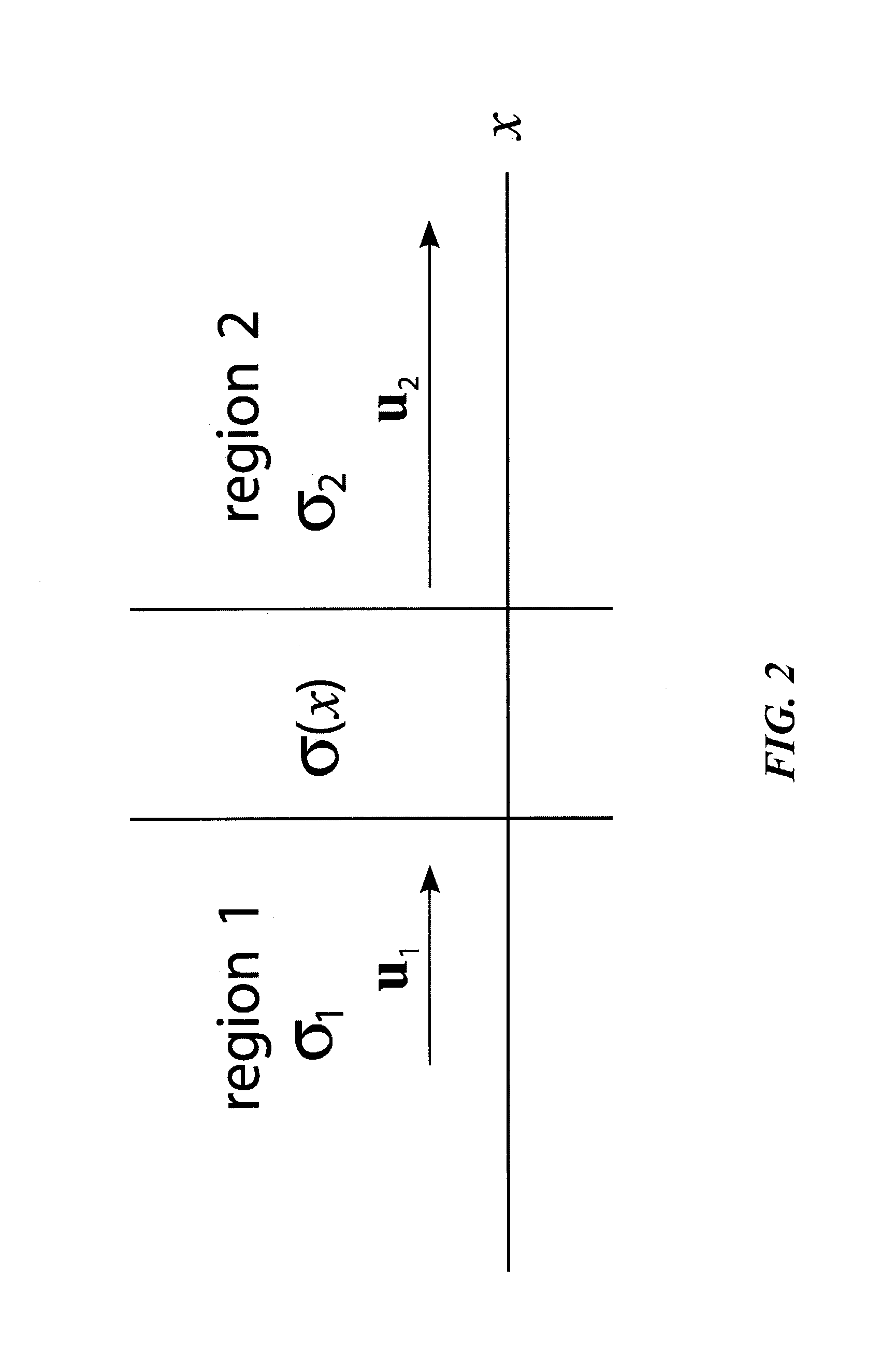
[0039]The invention can be best understood by considering the mathematics of conduction, which appear in many physical contexts, and is among the simplest and most thoroughly studied of any physical process. A new general method for designing fluid conduction channels is outlined as below and the resulting channels can, in turn, be applied to provide channel segments which will function as turns, splitters, combiners, manifolds, and expanders for electrokinetic or pressure driven flows.

[0040]Consideration is given to the depth-averaged properties of the fluid flow in three-dimensional fluid systems. For this reason, variations in the third dimension (depth) do not appear explicitly in the following discussion. This consideration is appropriate for channels having the planar properties outlined the Summary of Invention above. For clarity, we define the mathematical relations and apply semantics that are relevant to ideal electrokinesis. However, this semantic bias does not exclude th...


PUM

PropertyMeasurementUnit
critical flow-turning angleaaaaaaaaaa
flow velocity angleaaaaaaaaaa
critical turning angleaaaaaaaaaa

Abstract

A low-dispersion methodology for designing microfabricated conduction channels for on-chip electrokinetic-based systems is presented. The technique relies on trigonometric relations that apply for ideal electrokinetic flows, allowing faceted channels to be designed on chips using common drafting software and a hand calculator. Flows are rotated and stretched along the abrupt interface between adjacent regions with differing permeability. Regions bounded by interfaces form flow “prisms” that can be combined with other designed prisms to obtain a wide range of turning angles and expansion ratios while minimizing dispersion. Designs are demonstrated using two-dimensional numerical solutions of the Laplace equation.

Description

CROSS REFERENCE TO RELATED APPLICATIONS[0001]This application claims priority to, prior co-pending provisional U.S. Patent Application Ser. No. 60 / 387,684 originally filed Jun. 10, 2002 entitled “METHOD FOR PROVIDING CONDUCTION-LIKE FLOW CHANNELS AND APPLICATION THEREFOR” from which benefit is claimed.STATEMENT OF GOVERNMENT INTEREST[0002]This invention was made with Government support under government contract no. DE-AC04-94AL85000 awarded by the U.S. Department of Energy to Sandia Corporation. The Government has certain rights in the invention, including a paid-up license and the right, in limited circumstances, to require the owner of any patent issuing in this invention to license others on reasonable terms.BACKGROUND OF THE INVENTION[0003]Many engineering functions and / or analytical processes require moving a fluid. These tasks are increasingly utilizing systems that rely on one or more fluid channels having cross-sectional dimensions ranging from a few thousand to a few tens o...

Claims


Application Information

Patent Timeline
Patent Type & Authority Patents(United States)
IPC IPC(8): B01L3/02B01F5/06B01F13/00B01J19/00B01L3/00G01N27/447G01N30/28G01N30/60
CPCB01F5/0646B01F13/0059B01J19/0093B01L3/502746G01N30/6086B01F5/0648Y10T436/2575B01J2219/00783B01J2219/00891B01J2219/00916B01J2219/00995B01J2219/00997B01L2300/0861B01L2400/0415B01L2400/0487B01L2400/084B01L2400/086G01N27/44756G01N2030/285B01F25/4332B01F25/433B01F33/30
Inventor CUMMINGS, ERIC B.FIECHTNER, GREGORY J.
Owner SANDIA NAT LAB
Why Eureka
Try Eureka