Electromagnetic suspension system for vehicle

a suspension system and electromagnetic technology, applied in the direction of shock absorbers, motor/generator/converter stoppers, dynamo-electric converter control, etc., can solve the problems of degrading energy efficiency, changing between active control and passive control, and complicating active control but effective overcome drawbacks, simplifying active control, improving energy efficiency

Active Publication Date: 2006-02-28
NISSAN MOTOR CO LTD
View PDF22 Cites 34 Cited by
  • Summary
  • Abstract
  • Description
  • Claims
  • Application Information

AI Technical Summary

Benefits of technology

[0004]It is, therefore, an object of the present invention to provide an improved electromagnetic suspension system for a vehicle, which can effectively overcome drawbacks encountered in conventional electromagnetic suspension systems for vehicles.
[0005]Another object of the present invention is to provide an improved electromagnetic suspension system for a vehicle, which not only simplifies an active control for an electromagnetic actuator but also improves an energy efficiency.

Problems solved by technology

However, in such an electromagnetic suspension system, a changeover between the active control and the passive control is made.
This not only complicates the active control but also degrading an energy efficiency.

Method used


Image

  • Electromagnetic suspension system for vehicle
  • Electromagnetic suspension system for vehicle
  • Electromagnetic suspension system for vehicle

Examples


first embodiment

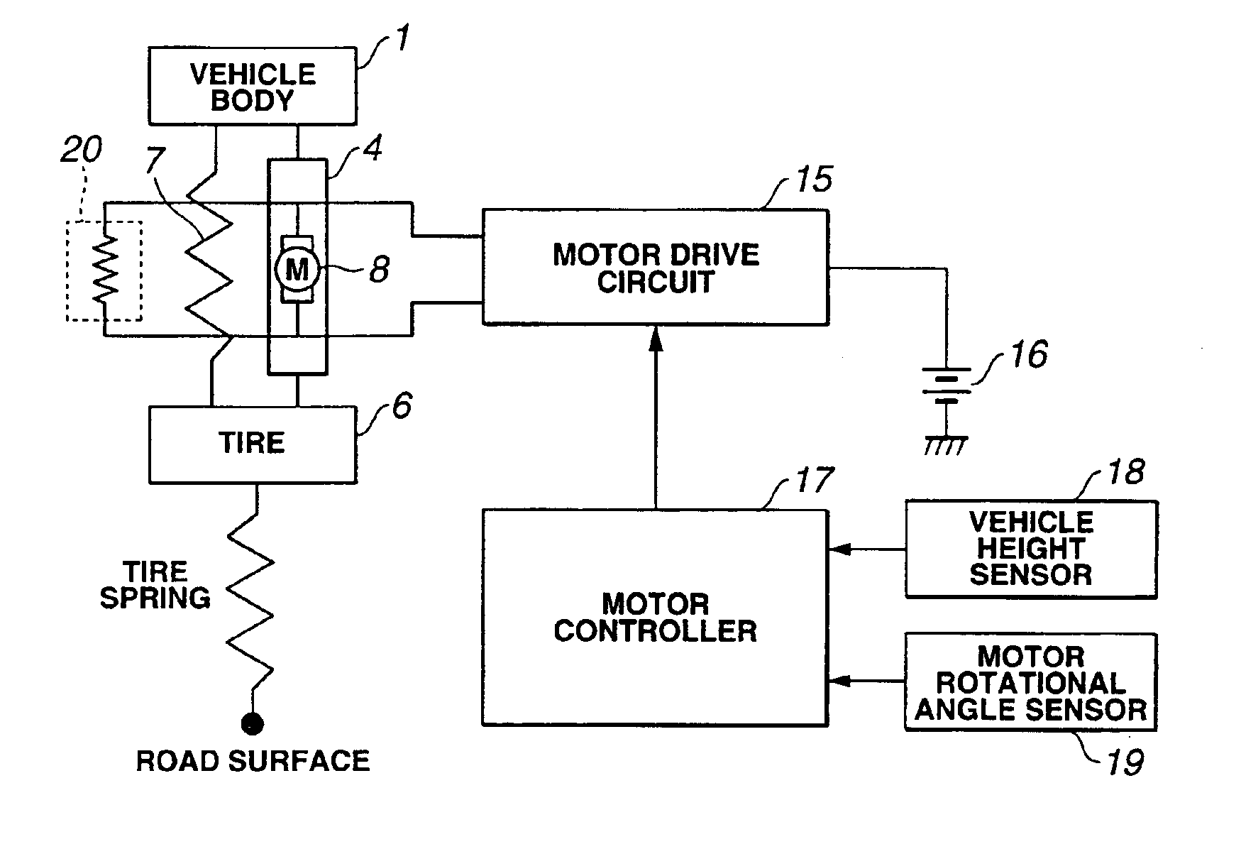
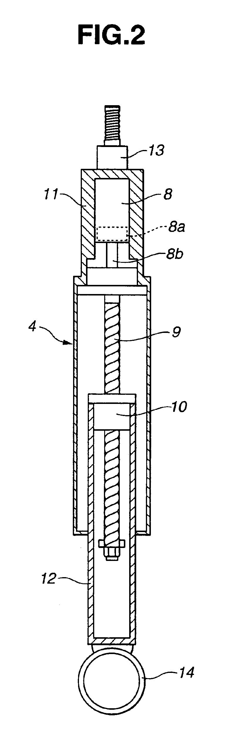
[0021]Electromagnetic actuator 4 will be discussed in detail hereinafter with reference to FIGS. 3 and 4. FIG. 3 is a block diagram illustrating a quarter vehicle body model having vertical two degrees of freedom, of the first embodiment electromagnetic suspension system and a motor control system for electromagnetic actuator 4. FIG. 4 is a circuit diagram of a motor control circuit for electric motor 8 of electromagnetic actuator 4.

[0022]When the first embodiment electromagnetic suspension system is represented as the quarter vehicle body model having vertical two degrees of freedom, spring element 7 and electromagnetic actuator 4 are arranged parallel with each other and interposed between vehicle body 1 as the sprung mass and tire 6 as the unsprung mass. Additionally, a tire spring is provided between tire 6 and the surface of road. Motor drive circuit 15 is electrically connected to electric motor 8 to control the electric motor. Motor drive circuit 15 is electrically connected ...

second embodiment

[0054]At step S21, detection is made to obtain a variety of quantities of states required for executing the control rule for electric motor 8 or electromagnetic actuator 4 set in the second embodiment electromagnetic suspension system, or quantities of states by which the above variety of quantities of states can be calculated.

[0055]At step S22, vibration components having frequencies of not lower than the cutoff frequency, of vibrations input to electromagnetic actuator 4 is removed.

[0056]At step S23, the actuator power output f is calculated in accordance with a control rule intended for the vibrations having frequencies lower than the cutoff frequency is calculated.

[0057]At step S24, the current value im for electric motor 8, required to obtain the actuator power output f is calculated.

[0058]At step S25, a command value (control signal) for flowing current having the current value im to electric motor 8 calculated at step S24 is output to motor drive circuit 15, and a flow goes t...


PUM


Abstract

An electromagnetic suspension system for a vehicle, comprises an electromagnetic actuator interposed between a sprung mass and an unsprung mass and disposed substantially in parallel with an spring element. An electric motor is provided for driving the electromagnetic actuator. A motor controller is configured to calculate a displacement input applied to the electromagnetic actuator and to control the electric motor in a manner that the electromagnetic actuator generates an optimum damping force corresponding to the displacement input. A motor control circuit is provided for the electric motor, through which the electric motor is connected to the motor controller. Additionally, an electrical damping element is electrically connected to the motor control circuit and in parallel with the electric motor to generate a damping force in a passive manner under a dynamic braking of the electric motor in response to the displacement input to the electromagnetic actuator from the unsprung mass.

Description

BACKGROUND OF THE INVENTION[0001]This invention relates to improvements in an electromagnetic suspension system for a vehicle, including an electromagnetic actuator (called an electromagnetic damper) which makes vibration damping for a suspension under a power source of electricity and is employed in place of a hydraulic damper which makes vibration damping under a viscosity resistance of hydraulic fluid or oil.[0002]Conventional electromagnetic suspension systems for a vehicle interchangeably use an active control and a passive control under the action of a coil-connection changeover device. In the active control, a damping force is controlled by providing energy to an electromagnetic actuator from the outside. In the passive control, a damping force is obtained under a dynamic braking of an electric motor. Such an electromagnetic suspension system is disclosed in Japanese Patent Provisional Publication No. 2002-48189.SUMMARY OF THE INVENTION[0003]However, in such an electromagneti...

Claims


Application Information

Patent Timeline
Patent Type & Authority Patents(United States)
IPC IPC(8): H02P3/12B60G17/015B60G17/00B60G13/02B60G13/14B60G17/0165F16F15/02F16F15/03
CPCB60G17/0165F16F15/035B60G13/02B60G13/14B60G17/0157B60G2202/42B60G2300/60B60G2400/206B60G2400/91B60G2500/10B60G2600/02B60G2600/09B60G2800/162B60G2800/916B60G2300/50
Inventor HIO, KOJISATO, MASAHARUUNO, TAKAAKI
Owner NISSAN MOTOR CO LTD
Why Eureka
Try Eureka