Metrology system with spectroscopic ellipsometer and photoacoustic measurements

Inactive Publication Date: 2006-02-28
RUDOLPH TECHNOLOGIES INC
View PDF22 Cites 23 Cited by
  • Summary
  • Abstract
  • Description
  • Claims
  • Application Information

AI Technical Summary

Benefits of technology

[0023]Yet another feature of the present invention is a method in which the ellipsometer is used to calculate the optical constants of an opaque film to improve the model for calculating the film thickness using the photoacoustic system.
[0024]Yet another feature of the present invention is a method in which both the ellipsometer and photoacoustic system are used in the steps to measure, calculate and report the film thickness, the results of the measurements being combined to provide an improved result.

Problems solved by technology

However, these separate pieces of equipment each require their own installation space in a semiconductor fabrication plant, which leads to a high overhead cost of the plant.

Method used


Image

  • Metrology system with spectroscopic ellipsometer and photoacoustic measurements
  • Metrology system with spectroscopic ellipsometer and photoacoustic measurements
  • Metrology system with spectroscopic ellipsometer and photoacoustic measurements

Examples


Embodiment Construction

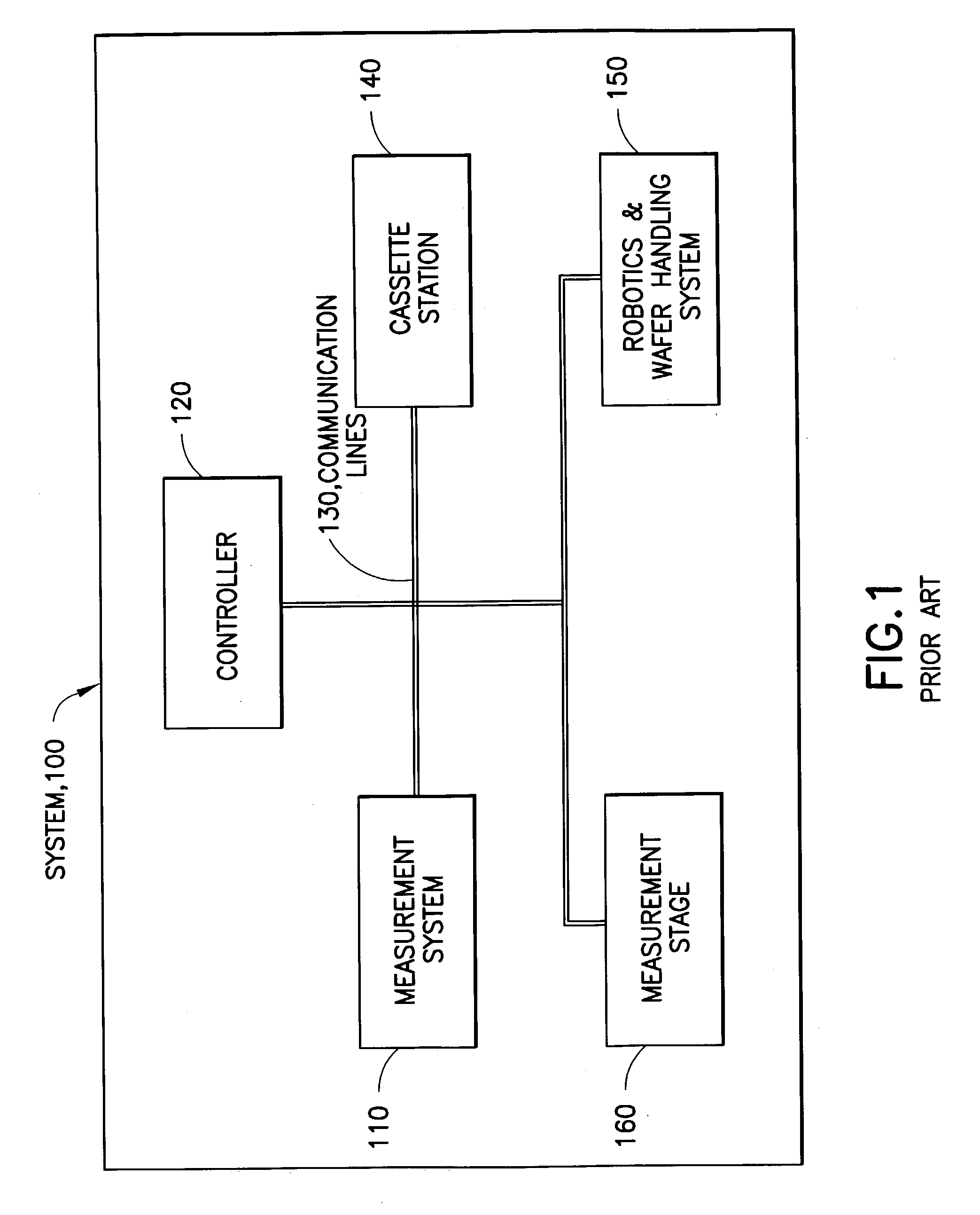
[0036]FIG. 1 shows a block diagram of a generalized prior art metrology system. Metrology system 100 comprises a measurement system 110, a controller 120, communication lines 130, a cassette station 140, a robotics & wafer handling system 150, and a measurement stage 160.

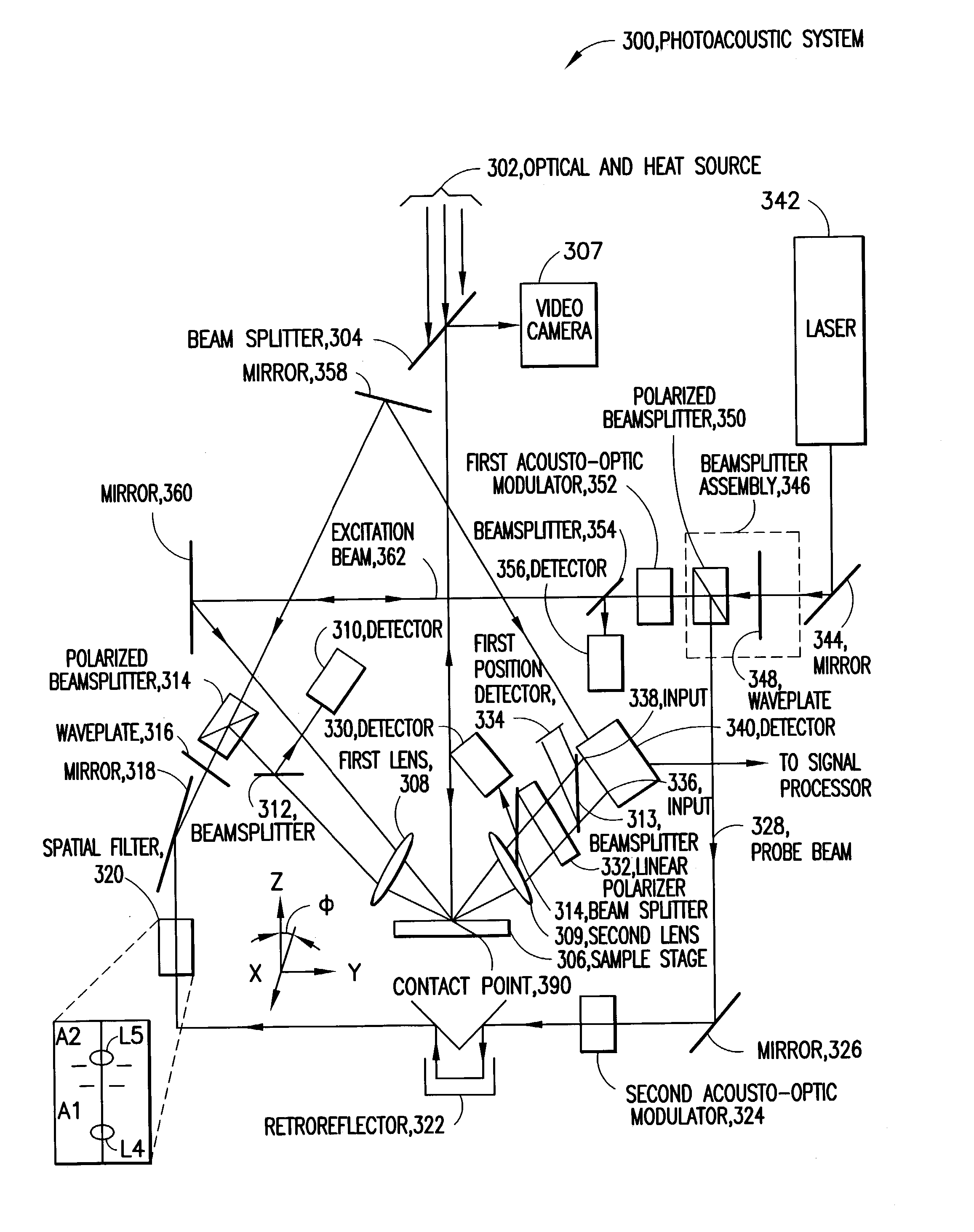
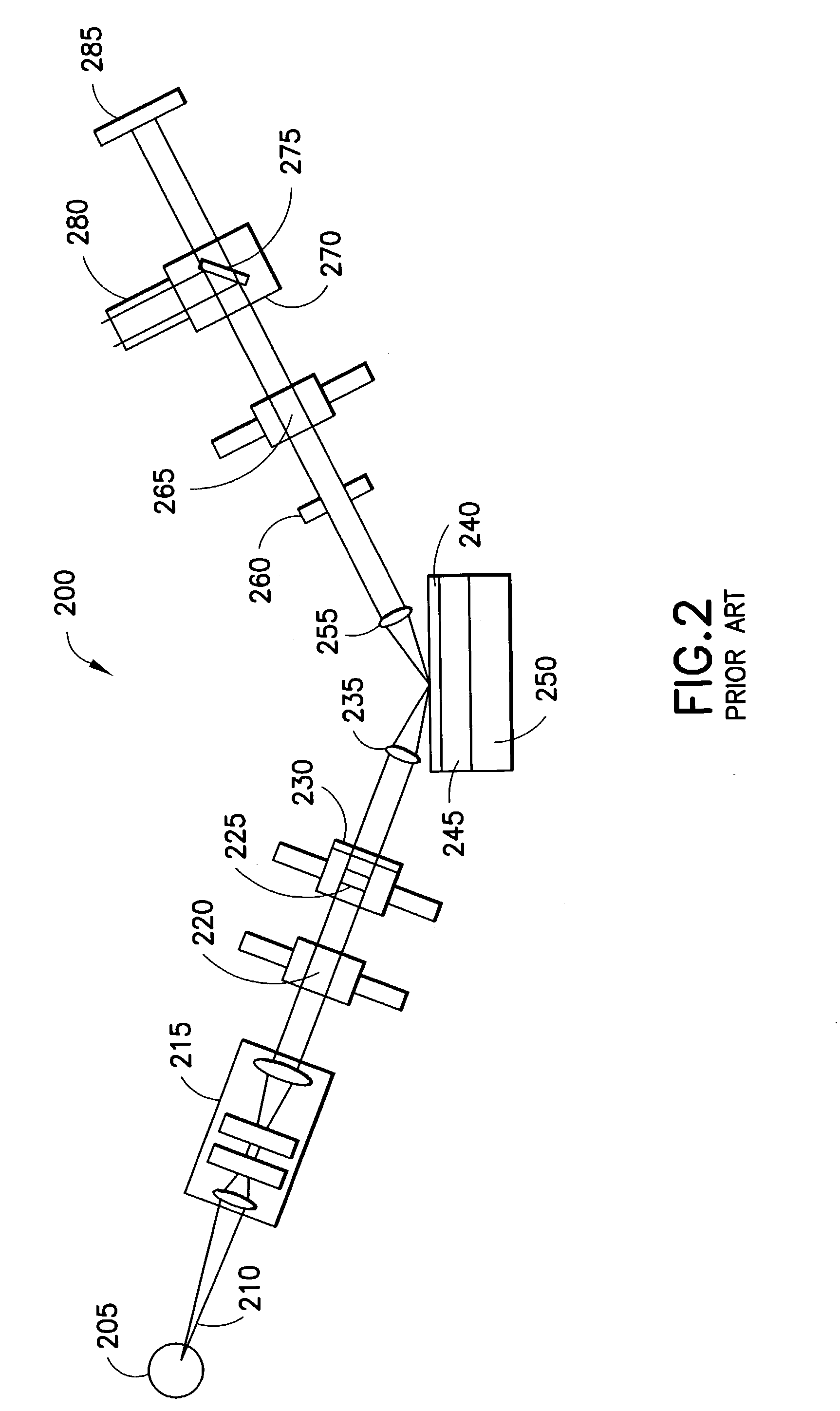
[0037]Measurement system 110 is either an ellipsometer or a photoacoustic system, as described in detail below. Measurement stage 160 comprises translation stages to position a wafer in a desired location beneath measurement system 110, and a translation stage to move the wafer toward or away from measurement system 110. Robotics and wafer handling system 150 comprises wafer gripping mechanisms, robots, and robotic controller system hardware and software to facilitate the transport of wafers from one location to another. Communication lines 130 are standard computer-to-instrument interface wires, fiber-optic cables, wireless, etc. Controller 120 comprises a computing device with a processor and memory. Controller 12...


PUM


Abstract

An optical system includes both a microspot broadband spectroscopic ellipsometer and a photoacoustic film thickness measurement system that are supplied laser light by the same laser light source. One of the systems makes a measurement, the result of which is used to adjust a parameter of the other system; e.g. the ellipsometer measures thickness and the photoacoustic system uses the thickness result to measure the speed of sound. In one version, the ellipsometer converts the laser beam to a broad-spectrum beam that provides higher intensity.

Description

CLAIM OF PRIORITY FROM PROVISIONAL PATENT APPLICATION[0001]This patent application claims priority under 35 U.S.C. §119(e) from Provisional Patent Application No.: 60 / 305,277, filed Jul. 13, 2001, and from Provisional Patent Application No.: 60 / 306,120, filed Jul. 17, 2001, the disclosures of which are incorporated by reference herein in their entireties.BACKGROUND OF THE INVENTION[0002]The semiconductor processing industry has made significant progress in recent years in forming ever-smaller minimum device geometries, which has created a need for processes that form very thin films. This development has in turn led to a need for metrology equipment to measure those films. In many process steps, the thickness of the thin films used to form these structures is becoming ever thinner. Gate oxide thicknesses, for example are now typically on the order of 10 to 20 Angstroms thick. One technique for measuring the thickness of such films is known as ellipsometry.[0003]Ellipsometry is a non...

Claims


Application Information

Patent Timeline
IPC IPC(8): G01J4/00G01N21/17G01N21/21
CPCG01B11/0666G01N21/211G01N21/1702G01N2021/1725
Inventor WOLF, ROBERT GREGORYMORATH, CHRISTOPHERMAIR, ROBIN
Owner RUDOLPH TECHNOLOGIES INC
Why Eureka
Try Eureka