Carbonaceous Chemistry for Continuum Modeling

Inactive Publication Date: 2011-03-10
THE UNITED STATES AS REPRESENTED BY THE DEPARTMENT OF ENERGY
View PDF0 Cites 10 Cited by
  • Summary
  • Abstract
  • Description
  • Claims
  • Application Information

AI Technical Summary

Benefits of technology

[0012]An object of the present invention is to provide a system for calculating rates of reactions for a given carbonaceous fuel under any gas-solid process. A feature of the invention is that calculates rates of reaction for all active chemical reactions occurring within a combustion/gasification chamber. An advantage of the present system is that it allows for improved modeling of the conversion of a carbonaceous fuel (e.g. coal) during combustion and gasification.
[0013]Another object of the present invention is to provide a combustion/gasification reactor model that does not rely on direct observation of smaller scale reactions. A feature of the present invention is that it can be applied to a fluid-dynamic (gas-solid) analytical field of any size under any operating condition (e.g. pressure, temperature, and flow rates).
[0014]Yet another object of the present invention is to provide a coal combustion/gasification reaction model having broad utility. A feature of the invention is that its initialization step generates a table of variables for a plurality of carbon-based fuels. An advantage of the invention is that it elucidates the chemistry of the combustion/gasification process upon input of the name and/or type of the fuel and other environmental variables.
[0015]Another object of the present invention is to provide a means to simultaneously monitor carbonaceous fuels reactivity and the surrounding flow field. A feature of the present invention is that it calculates the reaction rates of both the gas and the solid phases of carbonaceous fuel (e.g. coal) combustion/gasification while maintaining the values of the surrounding flow field as generated by the Eulerian-Eulerian fluid dynamics model. An advantage of the invention is that it combines the fluid dynamics mapping of the Eulerian-Eulerian model with a consideration of the chemical rea

Problems solved by technology

Unfortunately, new reactor designs to improve performance, chemical conversion, reliability, and safety have been slow to emerge due primarily to the lack of understanding of the complex hydrodynamics and chemical interactions between the gas and solids phases.
However, it is difficult to integrate this information into a comprehen

Method used


Image

  • Carbonaceous Chemistry for Continuum Modeling
  • Carbonaceous Chemistry for Continuum Modeling
  • Carbonaceous Chemistry for Continuum Modeling

Examples


Embodiment Construction

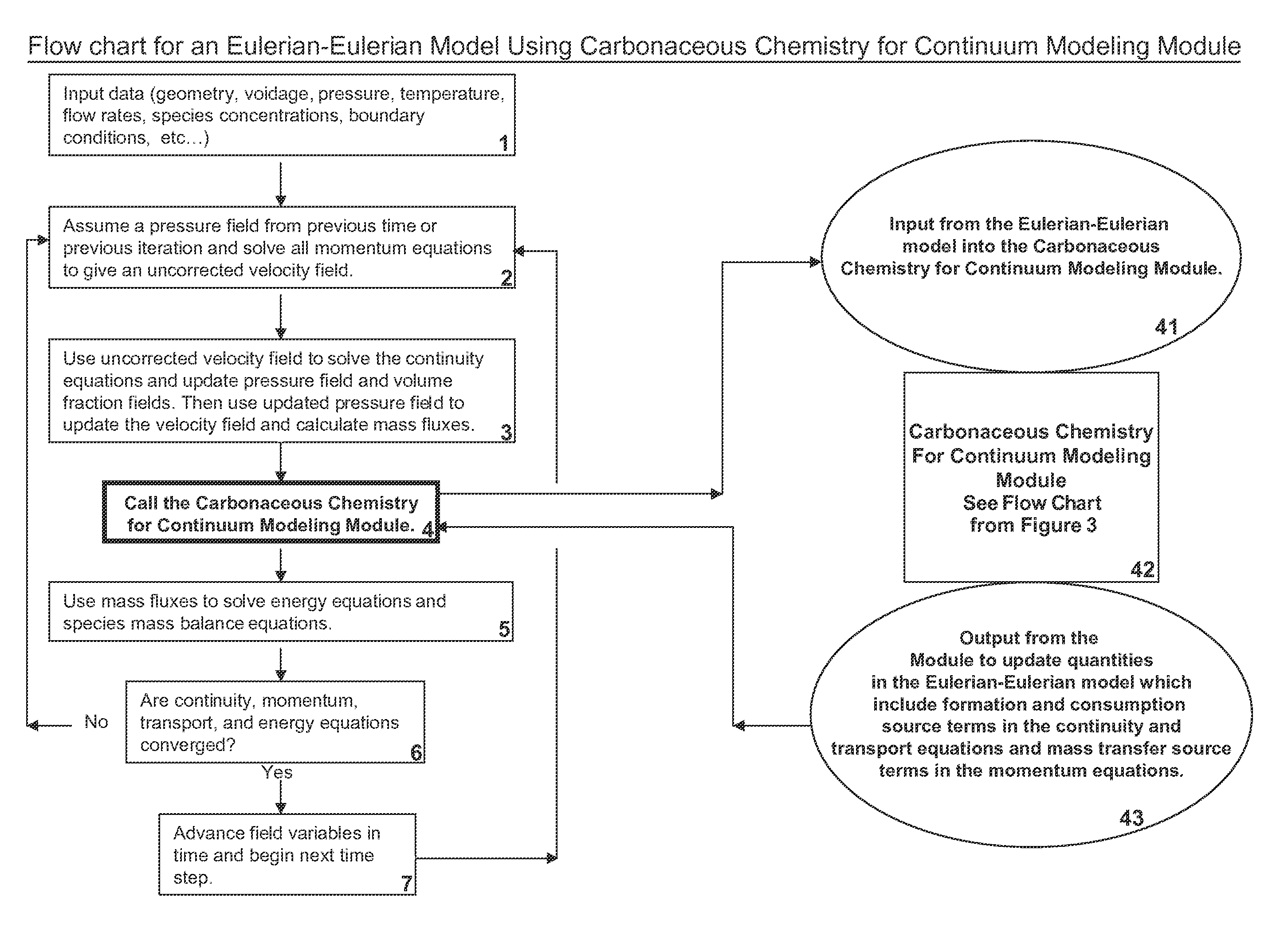
[0022]The invention is a method to couple the hydrodynamic behavior of a given reactor with the combustion / gasification chemistry of any carbonaceous fuel, the method comprising several steps. The first step involves producing or initializing of data stores for subsequent calculations. The initial calculations are due to devolatilization, moisture release, and tar cracking. The combustion / gasification calculations are the focus of subsequent steps.

[0023]Specifically, the present invention uses hydrodynamic data from an Eulerian-Eulerian model to elucidate reaction mechanisms for any carbonaceous fuel. An embodiment of the invention includes a means for receiving an input of gas and solids temperatures, gas pressures, gas and solids species mass fractions, voidage, solids volume fractions, gas density and viscosity, and gas and solids specific heats from an Eulerian-Eulerian model. Given this input, the module determines the heats of reactions, the rates of reactions related to coal ...


PUM


Abstract

A system and method of calculating fuel gasifier reactions is disclosed. The method and system model combustion/gasification within a gasifier by using an Eulerian-Eulerian flow field. The flow field is updated as the combustion/gasification progresses to account for the use of fuel as well as other reactions, mass transferred, and heat that occur within the gasifier during the combustion/gasification reactions.

Description

CROSS REFERENCE TO RELATED APPLICATIONS[0001]This application claims the benefit of U.S. Provisional Application No. 60 / 943,581 filed on Jun. 13, 2007.[0002]The United States Government has rights in this invention pursuant to Agreement between National Energy Technology Laboratory and the inventors and the employer-employee relationship of the U.S. Department of Energy and the inventors.BACKGROUND OF THE INVENTION[0003]1. Field of the Invention[0004]The present invention relates generally to a method for determining reaction rates within multiphase flow fields. More particularly the present invention relates to a method for determining the gasification and combustion reaction rates for any carbonaceous fuel (e.g. coal, biomass, oil shale, petcoke) in multiphase reactors.[0005]2. Background of the Invention[0006]Power plants of the future will use circulating fluidized bed (CFB) technology to gasify coal. Transport gasifiers will be a key component in the overall plant design of the...

Claims


Application Information

Patent Timeline
IPC IPC(8): G06G7/58G06F17/10G06F17/11
CPCC10J3/00C10J2300/06G06F19/702C10J3/723G16C20/10
Inventor GUENTHER, CHRISTOPHER PALMERSYAMLAL, MADHAVA
Owner THE UNITED STATES AS REPRESENTED BY THE DEPARTMENT OF ENERGY
Why Eureka
Try Eureka