
Motor system for sewing machine

a technology for sewing machines and motor systems, which is applied in the direction of sewing machine control devices, thin material processing, textiles and paper, etc., can solve the problems of large-scale fabrication costs and significant increase of the overall cost of the stopping position control motor system b>5/b> for the sewing machine, and achieve accurate stopping position control and cost reduction

Inactive Publication Date: 2006-03-07
CHIU YUNG HO
View PDF5 Cites 8 Cited by
  • Summary
  • Abstract
  • Description
  • Claims
  • Application Information

AI Technical Summary

Benefits of technology

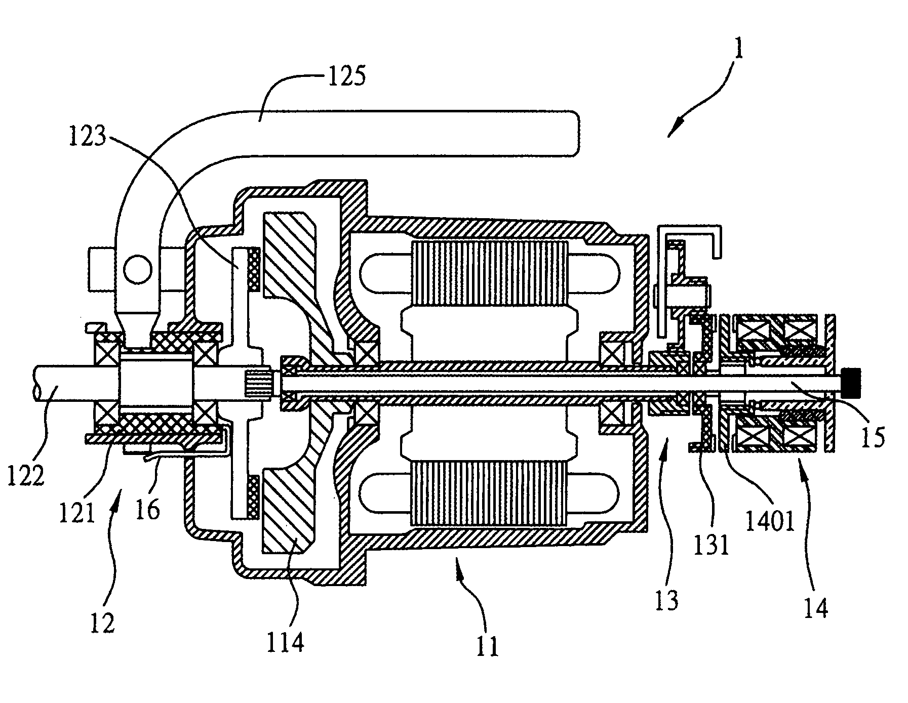
"The present invention provides a motor system for a sewing machine that can only use one motor to realize first and second speed controls, and a stopping position control. This reduces the cost of the motor system. The motor system includes a motor unit, an auxiliary driving shaft, a clutch unit, a speed changing unit, a position control unit, and a brake mechanism. The clutch unit can be coupled or separated from the motor unit, and the sliding disk can slide in the longitudinal direction with respect to the motor casing. The motor system can provide accurate stopping position control for the sewing mechanism. The motor system can be actuated by a drawbar or an electromagnetic driving mechanism. The technical effects of the present invention are to reduce the cost of the motor system and to provide accurate speed and stopping position controls for the sewing machine."

Problems solved by technology

Due to cost considerations, a motor for a sewing machine is generally an induction motor that can not perform a positioning control itself.
However, since the large-sized bearing 531 has a relatively large size and the large-sized gear disk 532 needs to cooperate with the deceleration motor shaft 534 to perform worm-gear processing, the fabrication cost of the large-sized bearing 531 and the large-sized gear disk 532 is relatively high, thereby making the overall cost of the stopping position control motor system 5 for the sewing machine significantly increased.

Method used


Image

  • Motor system for sewing machine
  • Motor system for sewing machine
  • Motor system for sewing machine

Examples


first preferred embodiment

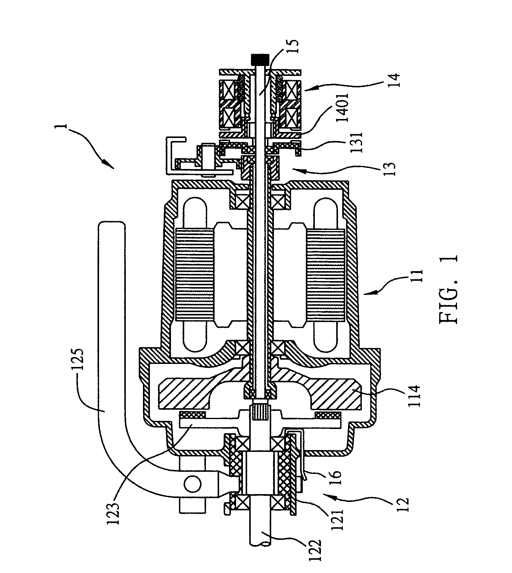
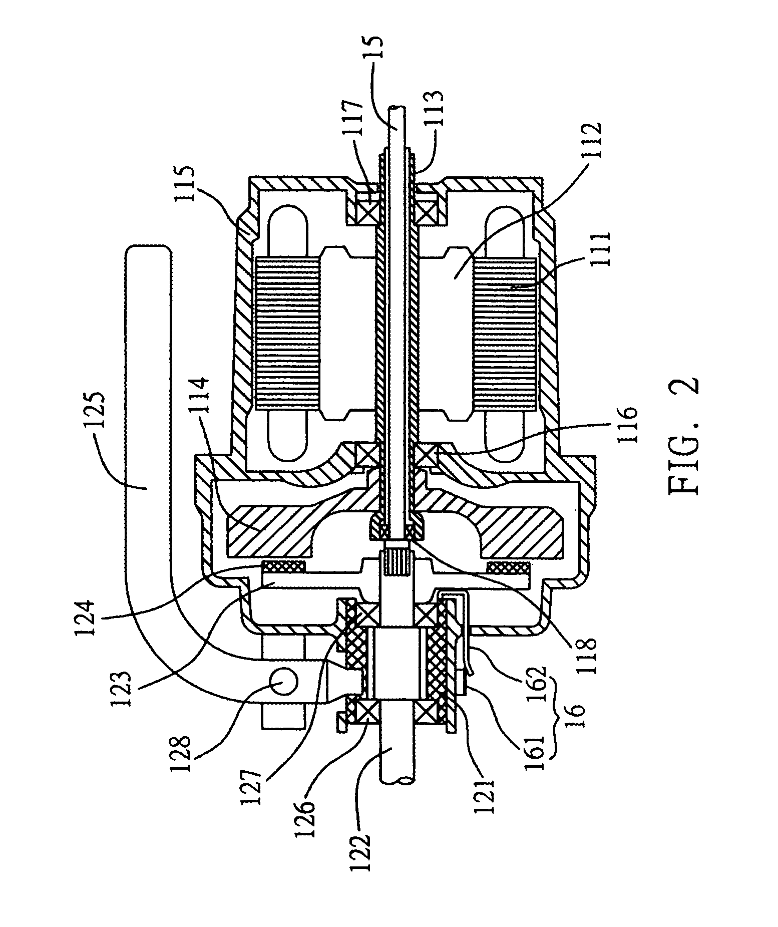
[0032]FIG. 1 is a cross-sectional view of a motor system for a sewing machine according to a first preferred embodiment of the present invention. FIG. 2 is an enlarged cross-sectional view showing a part of the motor system according to the first preferred embodiment of the present invention. FIG. 3 is an enlarged cross-sectional view showing another part of the motor system according to the first preferred embodiment of the present invention. FIG. 5 is a schematic diagram of the sewing machine with the motor system according to the present invention. Referring to FIGS. 1 and 5, the motor system 1 for a sewing machine according to the present invention comprises a motor unit 11, a clutch unit 12, a speed changing unit 13, a position control unit 14, an auxiliary driving shaft 15, a first sensor 16, and a second sensor 17.

[0033]As shown in FIG. 2, the motor unit 11 comprises a motor casing 115; a stator 111 and a rotor 112 that are accommodated within the motor casing 115; a hollow m...

second preferred embodiment

[0045]FIG. 4 is a cross-sectional view of a motor system 2 for a sewing machine according to a second preferred embodiment of the present invention. The motor system 2 in this embodiment is similar to the motor system 1 in the above first embodiment. Thus, only the differences between these two embodiments are described below. In FIG. 4, the same or similar components as or to those in FIG. 1 are designated with the same reference numerals.

[0046]As shown in FIG. 4, in the motor system 2 according to the second embodiment of the present invention, the drawbar 125 in the first embodiment is replaced by an automatic driving mechanism 229 having a driving plate 229-1 fixed on the sliding sleeve 121, and the sliding sleeve 121 is driven through the driving plate 229-1 of the automatic driving mechanism 229. The automatic driving mechanism 229 may be an electromagnetic driving mechanism or hydraulic driving mechanism, etc. Therefore, the sewing operation of the sewing machine can be stopp...


PUM


Abstract

A motor system for a sewing machine includes a motor unit rotatable at a first rotation speed; a clutch unit with an output shaft capable of being coupled to or separated from the motor unit; a speed changing unit for switching the first rotation speed to a second rotation speed; a position control unit with a sliding disk being movable to a first position, a second position or a third position, making the sliding disk rotate at the second or first rotation speed or stopped; an auxiliary driving shaft for transmitting the rotation of the sliding disk to the output shaft; a first sensor for detecting the position of the clutch unit; and a second sensor for detecting the position of a sewing mechanism of the sewing machine. Thereby, a first speed control, a second speed control and a stopping position control can be achieved for the sewing mechanism.

Description

FIELD OF THE INVENTION[0001]The present invention relates to motor systems for sewing machines, and more particularly, to a motor system that can only use one motor to realize a first speed control, a second speed control and a stopping position control for a sewing mechanism of a sewing machine.BACKGROUND OF THE INVENTION[0002]Since electric sewing can accurately control a sewing speed, increase the throughput and improve the sewing quality, most industrial sewing machines and household sewing machines have been equipped with electric motors to become electric sewing machines. A sewing mechanism of the electric sewing machine is typically driven by the motor via a belt. Generally, when stopping a sewing operation of the sewing machine, it is expected that a needle of the sewing mechanism can be held right at its topmost position, such that a maximum space exists between the needle and an underneath seat of the sewing machine to allow easy movement of a fabric being sewn or change o...

Claims


Application Information

Patent Timeline
Patent Type & Authority Patents(United States)
IPC IPC(8): D05B69/36
CPCD05B69/22D05B69/125
Inventor CHIU, YUNG-HO
Owner CHIU YUNG HO
Learn More