Fabric with three vertically stacked wefts with twinned forming wefts

a technology of twinned forming wefts and fabric, applied in the field of papermaking arts, can solve the problems of short fabric life, poor fabric quality and machine efficiency, common fabric deficiency is a characteristic diagonal, etc., and achieves more cross-directional stability and stiffness, and extra stability in the cross-direction. , the effect of improving the drainage properties of the fabri

Inactive Publication Date: 2006-03-07
ALBANY INT CORP
View PDF24 Cites 20 Cited by
  • Summary
  • Abstract
  • Description
  • Claims
  • Application Information

AI Technical Summary

Benefits of technology

[0023]To provide more cross-directional stability and stiffness, the invention utilizes a third set of wefts, in the middle layer of the fabric, to provide extra stability in the cross direction.
[0024]The fabric is a forming fabric having a top layer, a middle layer, and a bottom layer of cross-machine direction (CD) wefts and a system of machine-direction (MD) warp yarns interwoven with the top, middle, and bottom layers of CD wefts. The CD wefts in the top layer are grouped into twinned pairs to produce a non-uniform spacing between wefts in the top layer. The CD wefts in the middle layer provide extra stability in the CD. The CD wefts in the middle layer and bottom lay

Problems solved by technology

However, forming fabrics also need to address water removal and sheet formation issues.
If drainage occurs too rapidly or too slowly, the sheet quality and machine efficiency suffers.
A fine mesh fabric may provide the desired paper surface and fiber support properties, but such design may lack the desired stability resulting in a short fabric life.
Due to the repeating nature of the weave patterns, a common fabric deficiency is a characteristic diagonal in the fabric.
However, a true random

Method used


Image

  • Fabric with three vertically stacked wefts with twinned forming wefts
  • Fabric with three vertically stacked wefts with twinned forming wefts
  • Fabric with three vertically stacked wefts with twinned forming wefts

Examples


Embodiment Construction

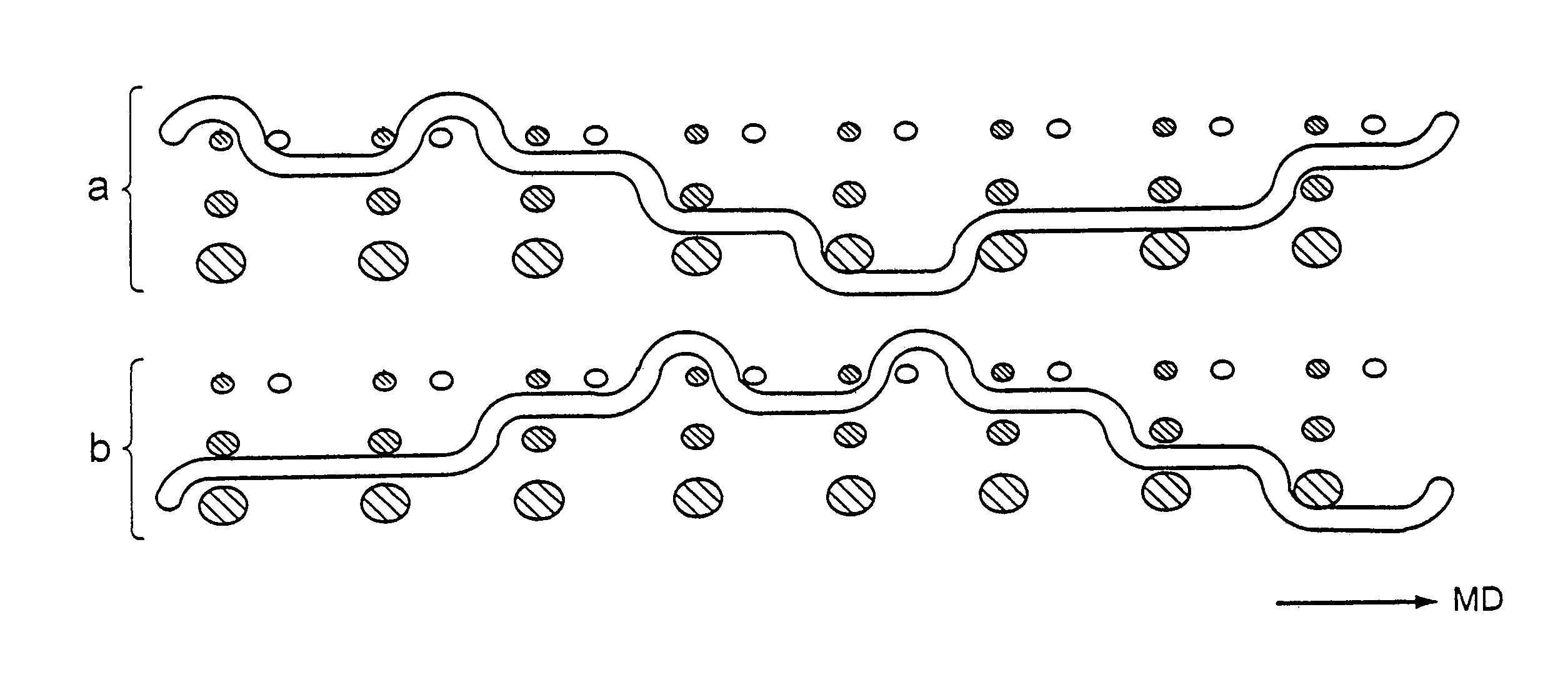
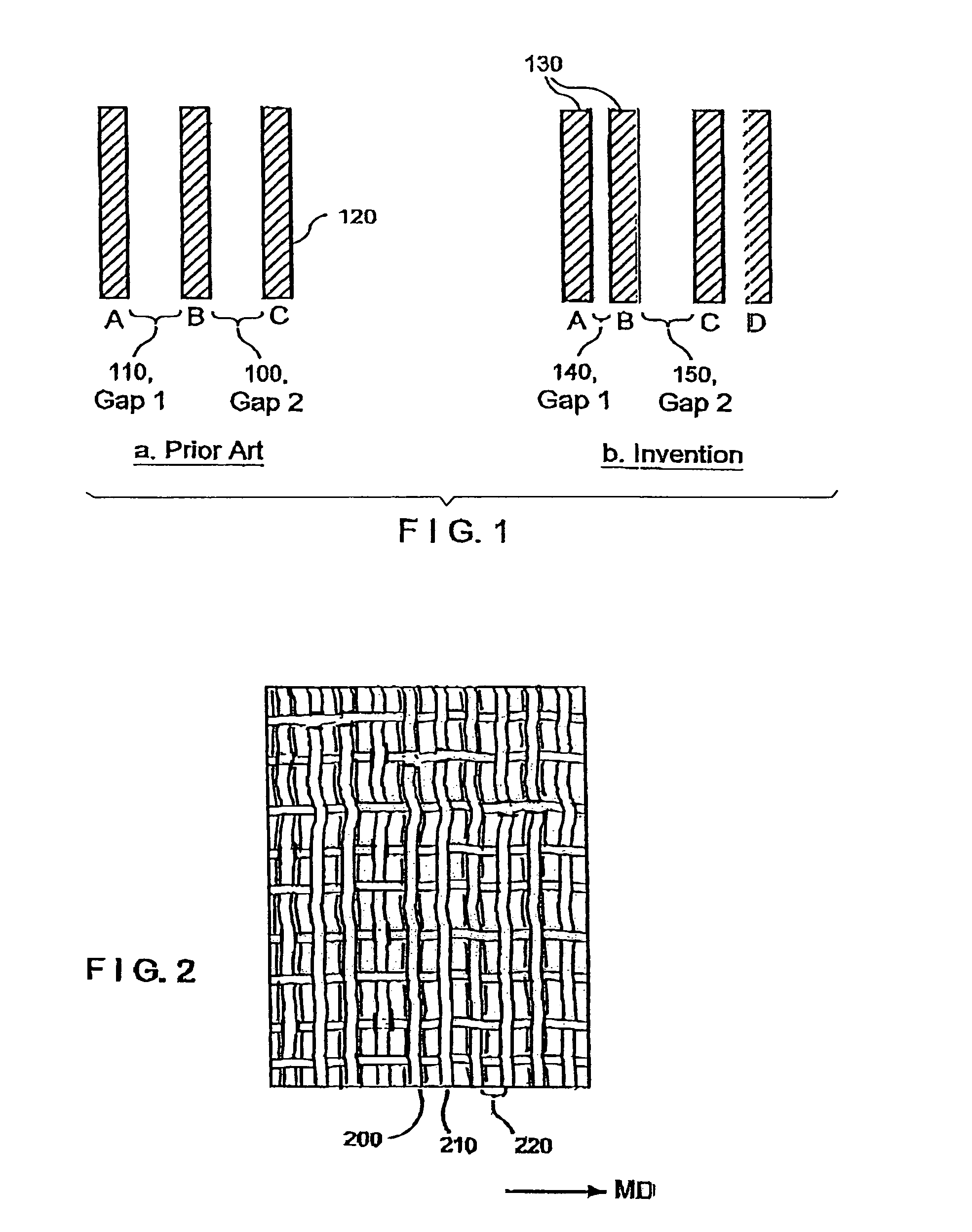
[0034]FIG. 1 is a schematic view providing a comparison between the weft / shute spacing in the top (or forming) layer of prior art fabrics and the present invention. Each vertical stripe in the figure represents a forming side weft. FIG. 1a shows the weft spacing according to the prior art, while FIG. 1b shows the weft spacing according to the present invention. Note that in FIG. 1a, the spacing of Gap 1110 is approximately equal to the spacing of Gap 2100. Whereas, in FIG. 1b, the wefts are unevenly spaced. Because of the uneven spacing between wefts A and B, and B and C; wefts A and B are characterized as twinned, or paired, wefts 130. This twinning / pairing is considered beneficial as the non-uniform spacing helps promote drainage and conceals the diagonal sheet mark.

[0035]A sample forming fabric has been produced in accordance with the teachings of the present invention. Measurements taken from this sample fabric show that the forming side wefts 120 have a cross-sectional diameter...


PUM

PropertyMeasurementUnit
Stabilityaaaaaaaaaa

Abstract

A papermaker's fabric, usable in the forming section of a paper machine, has three layers of cross-machine-direction (CD) wefts. The forming layer wefts are grouped into pairs. This twinning of the top-layer wefts results in non-equal spacing in the forming layer. This spacing imparts a desired non-uniformity in the web-supporting surface, thereby reducing the fabric diagonal problem. One of the top-layer wefts in each pair is vertically stacked with the middle and wear side layer wefts. The other top-layer wefts in each pair are unstacked. This alignment increases the drainage properties of the fabric. The middle layer wefts provide extra stability in the CD.

Description

BACKGROUND OF THE INVENTION[0001]1. Field of the Invention[0002]The present invention relates to the papermaking arts. More specifically, the present invention relates to forming fabrics for the forming section of a paper machine.[0003]2. Description of the Prior Art[0004]During the papermaking process, a cellulosic fibrous web is formed by depositing a fibrous slurry, that is, an aqueous dispersion of cellulose fibers, onto a moving forming fabric in the forming section of a paper machine. A large amount of water is drained from the slurry through the forming fabric, leaving the cellulosic fibrous web on the surface of the forming fabric.[0005]The newly formed cellulosic fibrous web proceeds from the forming section to a press section, which includes a series of press nips. The cellulosic fibrous web passes through the press nips supported by a press fabric, or, as is often the case, between two such press fabrics. In the press nips, the cellulosic fibrous web is subjected to compr...

Claims


Application Information

Patent Timeline
IPC IPC(8): D21F1/10D21F7/08D21F7/12D21F1/00
CPCD21F1/0036Y10S162/90Y10S162/902Y10S162/903Y10T442/3179Y10T442/3098Y10T442/3195D21F1/00D21F3/00D21F1/10
Inventor ROUGVIE, DAVID S.COLLEGNON, JEFFREY JOSEPHLAFOND, JOHN
Owner ALBANY INT CORP
Why Eureka
Try Eureka