Electronic devices having a header and antiparallel connected light emitting diodes for producing light from AC current

a technology of anti-parallax connection and light-emitting diodes, which is applied in the direction of electric variable regulation, process and machine control, instruments, etc., can solve the problems of low light output, large untapped market for white lighting applications, and relatively high initial installation cost, so as to eliminate the need for wire bonding and increase light output

Inactive Publication Date: 2006-03-07
IDEAL IND LIGHTING LLC
View PDF48 Cites 455 Cited by
  • Summary
  • Abstract
  • Description
  • Claims
  • Application Information

AI Technical Summary

Benefits of technology

[0012]Other embodiments of the invention provide a light engine comprising a single insulating or semi-insulating substrate having formed thereon plural LED active elements with associated p- and n-type contacts forming a cathode and an anode, respectively, for each LED active element. The device may be mounted in a flip-chip configuration to increase light Output and potentially eliminate the need for wirebonding.

Problems solved by technology

Although the initial cost of installation is relatively high, LED-based traffic signals have, generally, a substantially longer operational life and a far lower cost per lumen than traditional incandescent bulbs.
Despite the availability of solid state white light sources, the vast majority of the market for white lighting applications (namely, home and office lighting) remains relatively untapped.
Part of the reason for this is that LEDs are typically not directly compatible with existing power distribution networks.
However connection of packaged LEDs in this configuration typically consumes an excessive amount of space.
Moreover, the system designer may need to design complex interconnections within the luminaire to implement this design using available LED technology.

Method used


Image

  • Electronic devices having a header and antiparallel connected light emitting diodes for producing light from AC current
  • Electronic devices having a header and antiparallel connected light emitting diodes for producing light from AC current
  • Electronic devices having a header and antiparallel connected light emitting diodes for producing light from AC current

Examples


Embodiment Construction

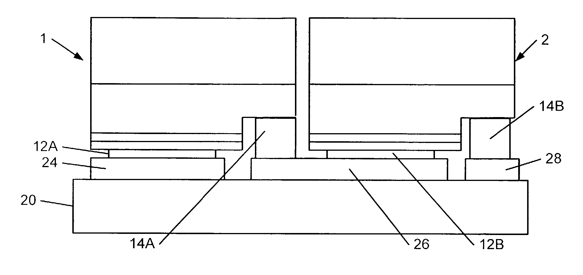
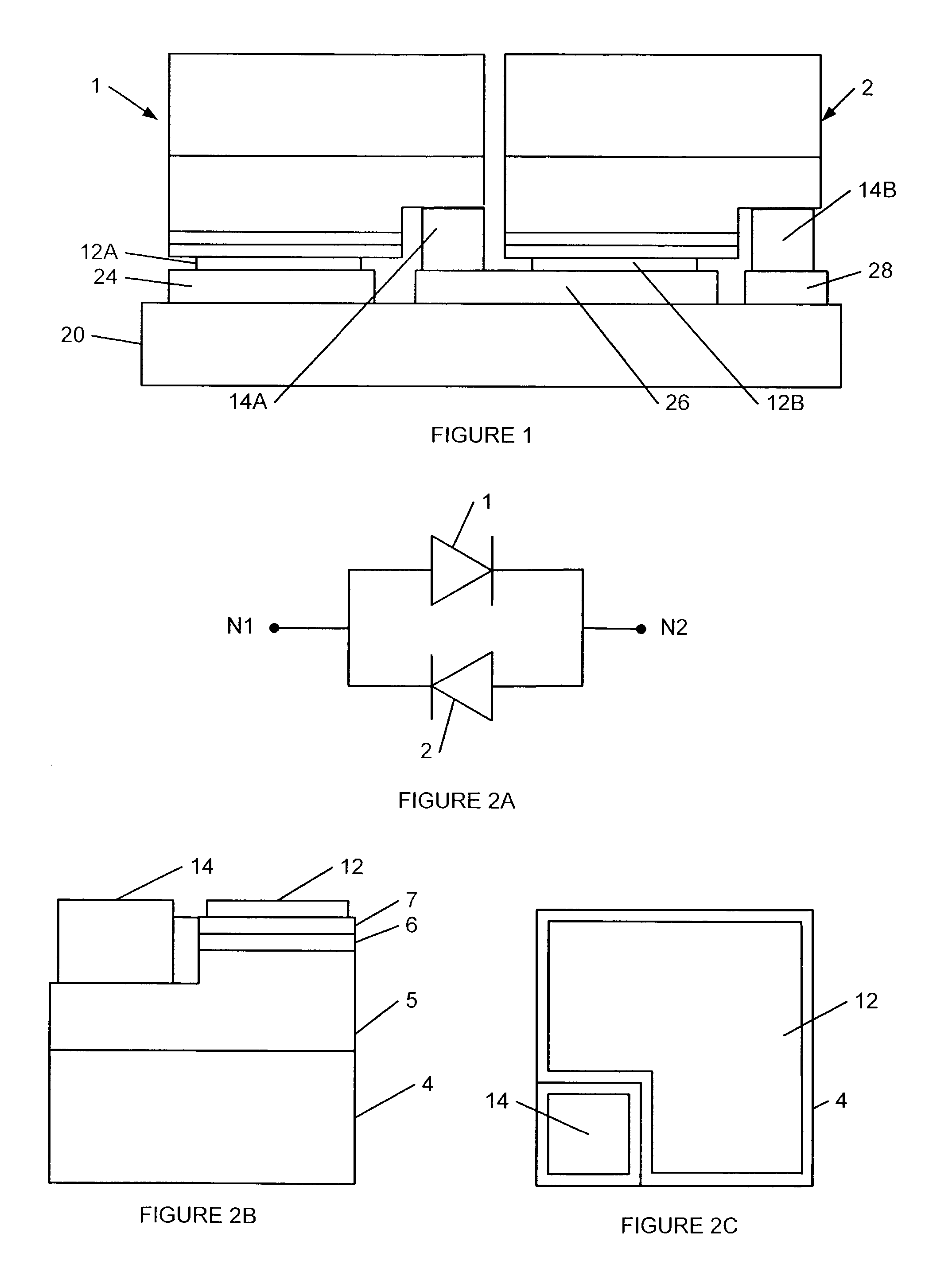
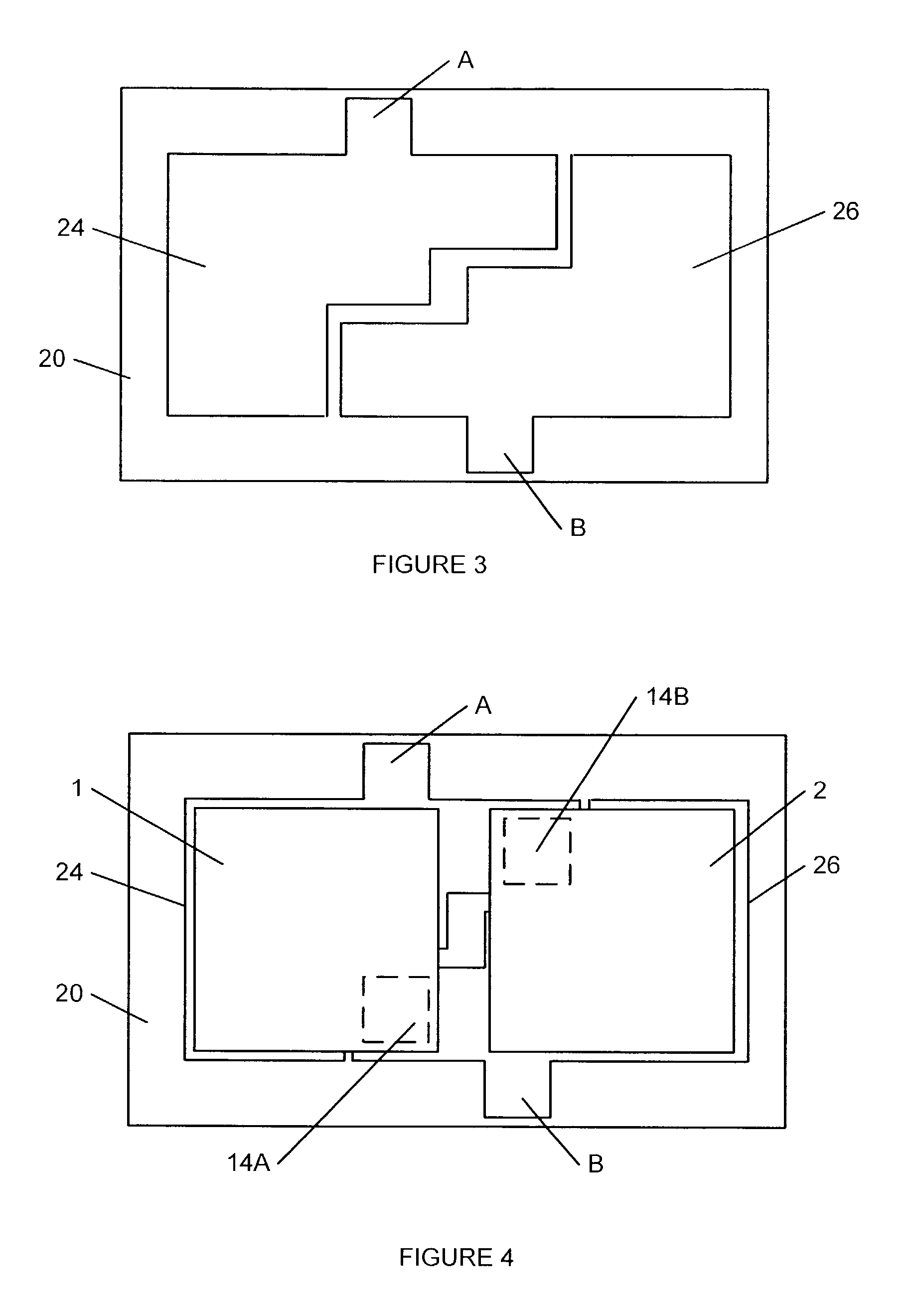
[0028]The present invention now will be described more fully hereinafter with reference to the accompanying drawings, in which embodiments of the invention are shown. This invention should not be construed as limited to the embodiments set forth herein; rather, these embodiments are provided so that this disclosure will be thorough and complete, and will fully convey the scope of the invention to those skilled in the art. Like numbers refer to like elements throughout. Furthermore, the various layers and regions illustrated in the figures are illustrated schematically. As will also be appreciated by those of skill in the art, while the present invention is described with respect to semiconductor wafers and diced chips, such chips may be diced into arbitrary sizes. Accordingly, the present invention is not limited to the relative size and spacing illustrated in the accompanying figures. In addition, certain features of the drawings are illustrated in exaggerated dimensions for clarit...


PUM


Abstract

A light engine comprises a pair of LED active elements mounted on a common header having first and second terminals. The first terminal is connected to the cathode of the first LED active element and the anode of the second LED active element, while the second terminal is connected to the anode of the first LED active element and the cathode of the second LED active element, thereby connecting the LEDs in an anti-parallel arrangement. A light engine having a single insulating or semi-insulating substrate having formed thereon plural LED active elements with associated p- and n-type contacts forming cathode and anode contacts, respectively, for each LED active element is also provided. The LED active elements may be mounted in a flip-chip configuration on a header having a plurality of leads. The header may include a pair of leads adapted such that two LEDs may be flip-mounted thereon with the anode of the first LED and the cathode of the second LED contacting one lead, while the cathode of the first LED and the anode of the second LED contact the other lead. In addition, the header may be adapted to permit a substrate having multiple active elements to be mounted thereon.

Description

FIELD OF THE INVENTION[0001]This invention relates to microelectronic devices and fabrication methods therefor, and more particularly to light emitting diodes (LEDs) and manufacturing methods therefor.BACKGROUND[0002]Light emitting diodes are widely used in consumer and commercial applications. As is well known to those having skill in the art, a light emitting diode generally includes a diode region on a microelectronic substrate. The microelectronic substrate may comprise, for example, silicon, gallium arsenide, gallium phosphide, alloys thereof, silicon carbide and / or sapphire. Continued developments in LEDs have resulted in highly efficient and mechanically robust light sources that can cover the visible spectrum and beyond. These attributes, coupled with the potentially long service life of solid state devices, low cost of operation, low heat generation, increased efficiency and other benefits may enable a variety of new display applications, and may place LEDs in a position to...

Claims


Application Information

Patent Timeline
Patent Type & Authority Patents(United States)
IPC IPC(8): H01L33/00H01L25/075H01L33/20
CPCH01L25/0753H01L33/20H01L2924/0002H01L2924/00
Inventor HALL, DAVID CHARLES
Owner IDEAL IND LIGHTING LLC
Why Eureka
Try Eureka