[0012]A first object of the present invention is to provide a spread spectrum receiver enabling the design of
power efficient spread spectrum systems with a very high
chip rate, where the complexity of the circuit is independent of the chip rate and capable of reducing the associated
power consumption.
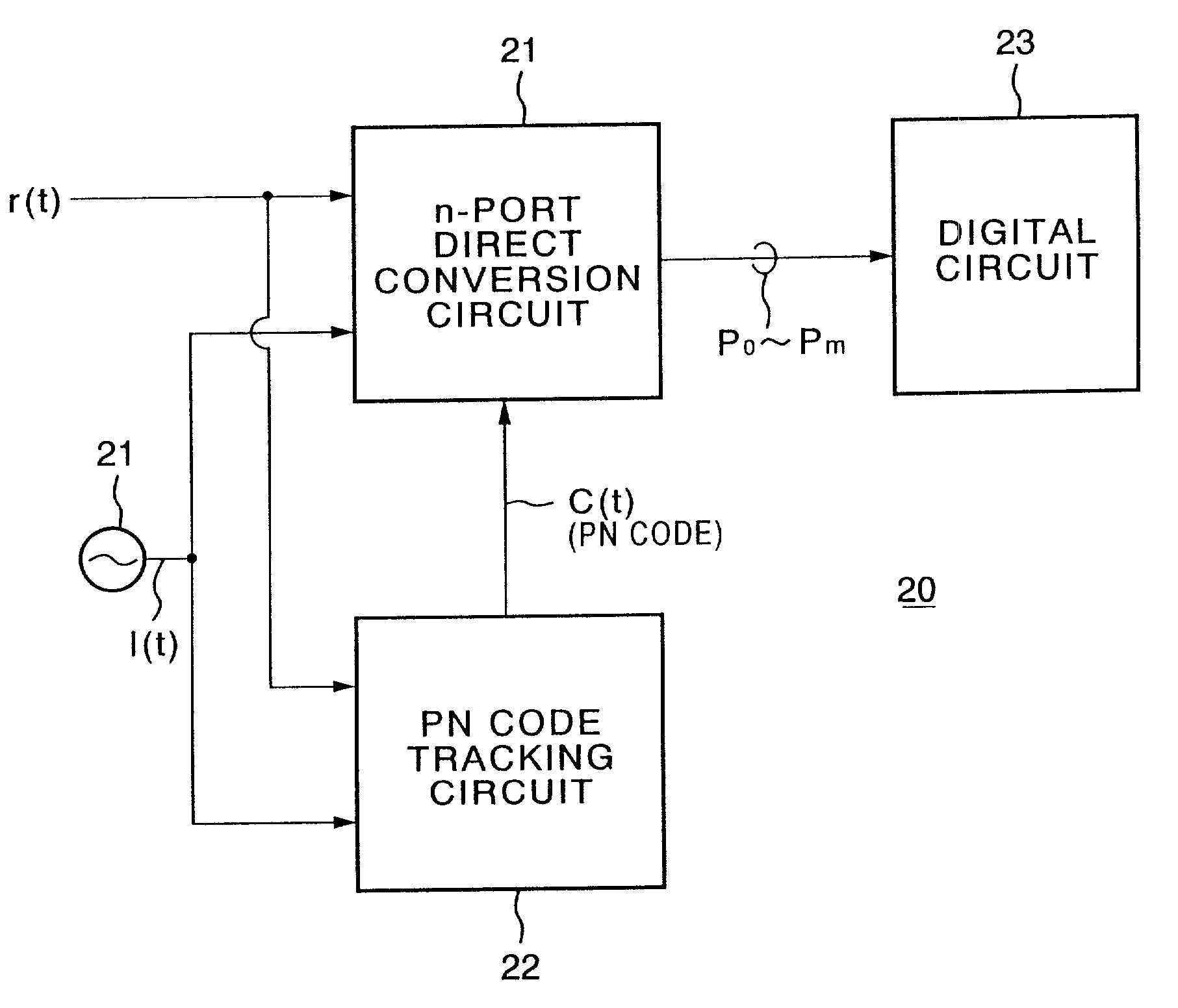
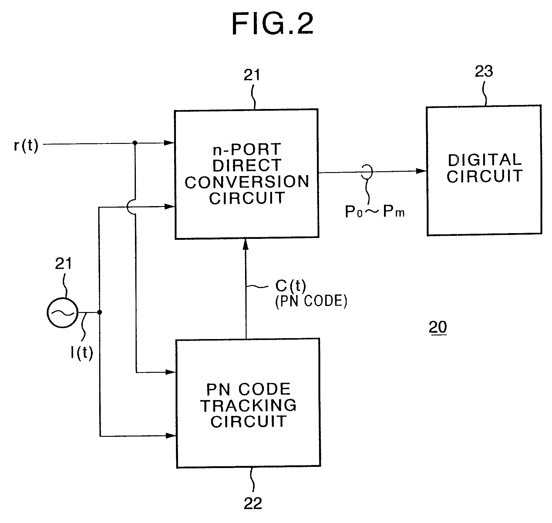
[0023]Preferably, the local spreading
code tracking means comprises a local spreading code generator for generating the local spreading code based on a value of a
control signal, a first phase adjusting means for delaying the generated local spreading code by a predetermined time, a second phase adjusting means for advancing the generated local spreading code by a predetermined time, a first multiplier for multiplying the local
signal by an output of the first phase adjusting means, a second multiplier for multiplying the local
signal by an output of the second phase adjusting means, a first
adder for adding the received signal and an output of the first multiplier, a first
detector for detecting an amplitude component of an output signal of the first
adder, a first envelope detecting means for detecting a first envelope of an output signal of the first
detector, a second
adder for adding the received signal and an output of the second multiplier, a second
detector for detecting an amplitude component of an output signal of the second adder, a second envelope detecting means for detecting a second envelope of an output signal of the second detector, and a
control signal generating means for generating the
control signal so as to reduce the difference between the first envelope and second envelope close to zero.
[0024]Further, the local spreading
code tracking means comprises a local spreading code generator for generating the local spreading code based on a value of a control signal, a first phase adjusting means for delaying the generated local spreading code by a predetermined time, a second phase adjusting means for advancing the generated local spreading code by a predetermined time, a first multiplier for multiplying the local signal by an output of the first phase adjusting means, a second multiplier for multiplying the local signal by an output of the second phase adjusting means, a first phase shifter for shifting the received signal in phase, a second phase shifter for shifting an output signal of the first multiplier in phase, a
third phase shifter for shifting an output signal of the second multiplier in phase, a fourth phase shifter for shifting the received signal in phase, a first adder for adding an output signal of the first phase shifter and the output of the first multiplier, a second adder for adding the received signal and an output signal of the second phase shifter, a third adder for adding the received signal and an output signal of the
third phase shifter, a fourth adder for adding the output signal of the second multiplier and an output signal of the fourth phase shifter, a first detector for detecting a
signal level of an output of the first adder, a second detector for detecting a
signal level of an output of the second adder, a third detector for detecting a
signal level of an output of the third adder, a fourth detector for detecting a signal level of an output of the fourth adder, a first filter for performing a predetermined filtering
processing with respect to an output of a first detector, a second filter for performing a predetermined filtering processing with respect to an output of a second detector, a third filter for performing a predetermined filtering processing with respect to an output of a third detector, a fourth filter for performing a predetermined filtering processing with respect to an output of a fourth detector, a first norm circuit for computing a first norm based on outputs of the first and second filters, a second norm circuit for computing a second norm based on outputs of the third and fourth filters, a control signal generating means for generating the control signal so as to reduce the difference between the first norm and second norm close to zero.
[0027]Further, the local spreading
code tracking means comprises: a first local spreading code generator for generating an in-phase local spreading code based on a value of a control signal, a second local spreading code generator for generating a quadration local spreading code based on the value of a control signal, a first phase adjusting means for delaying the generated in-phase and quadrature local spreading codes by a predetermined time, a second phase adjusting means for advancing the generated in-phase and quadrature local spreading codes by a predetermined time, a first
quadrature modulator for modulating the local signal by output signals of the first phase adjusting means, a second
quadrature modulator for modulating the local signal by output signals of the second phase adjusting means, a first phase shifter for shifting the received signal in phase, a second phase shifter for shifting an output signal of the first
quadrature modulator in phase, a
third phase shifter for shifting an output signal of the second quadrature modulator in phase, a fourth phase shifter for shifting the received signal in phase, a first adder for adding an output signal of the first phase shifter and the output of the first quadrature modulator, a second adder for adding the received signal and an output signal of the second phase shifter, a third adder for adding the received signal and an output signal of the third phase shifter, a fourth adder for adding the output signal of the second quadrature modulator and an output signal of the fourth phase shifter, a first detector for detecting a signal level of an output of the first adder, a second detector for detecting a signal level of an output of the second adder, a third detector for detecting a signal level of an output of the third adder, a fourth detector for detecting a signal level of an output of the fourth adder, a first filter for performing a predetermined filtering processing with respect to an output of a first detector, a second filter for performing a predetermined filtering processing with respect to an output of a second detector, a third filter for performing a predetermined filtering processing with respect to an output of a third detector, a fourth filter for performing a predetermined filtering processing with respect to an output of a fourth detector, a first norm circuit for computing a first norm based on outputs of the first and second filters, a second norm circuit for computing a second norm based on outputs of the third and fourth filters, a control signal generating means for generating the control signal so as to reduce the difference between the first norm and second norm close to zero.
[0028]Further, the local spreading code tracking means comprises a first local spreading code generator for generating an in-phase local spreading code based on a value of a control signal, a second local spreading code generator for generating a quadration local spreading code based on the value of a control signal, a first phase adjusting means for delaying the generated in-phase local spreading code by a predetermined time, a second phase adjusting means for delaying the generated quadration local spreading code by a predetermined time, a third phase adjusting means for advancing the generated in-phase local spreading code by a predetermined time, a fourth phase adjusting means for advancing the generated quadration local spreading code by a predetermined time, a first multiplier for multiplying the local signal by an output signal of the first phase adjusting means, a second multiplier for multiplying the local signal by an output signal of the second phase adjusting means, a third multiplier for multiplying the local signal by an output signal of the third phase adjusting means, a fourth multiplier for multiplying the local signal by an output signal of the fourth phase adjusting means, a first adder for adding the received signal and an output signal of the first multiplier, a second adder for adding the received signal and an output signal of the second multiplier, a third adder for adding the received signal and an output signal of the third multiplier, a fourth adder for adding the received signal and an output signal of the fourth multiplier, a first detector for detecting a signal level of an output of the first adder, a second detector for detecting a signal level of an output of the second adder, a third detector for detecting a signal level of an output of the third adder, a fourth detector for detecting a signal level of an output of the fourth adder, a first filter for performing a predetermined filtering processing with respect to an output of a first detector, a second filter for performing a predetermined filtering processing with respect to an output of a second detector, a third filter for performing a predetermined filtering processing with respect to an output of a third detector, a fourth filter for performing a predetermined filtering processing with respect to an output of a fourth detector, a first norm circuit for computing a first norm based on outputs of the first and second filters, a second norm circuit for computing a second norm based on outputs of the third and fourth filters, and a control signal generating means for generating the control signal so as to reduce the difference between the first norm and second norm close to zero.
[0032]Preferably, the local spreading code tracking means comprises a first local spreading code generator for generating an in-phase local spreading code based on a value of a control signal, a second local spreading code generator for generating a quadration local spreading code based on the value of a control signal, a first phase adjusting means for delaying the generated in-phase and quadration local spreading codes by a predetermined time, a second phase adjusting means for advancing the generated in-phase and quadration local spreading codes by a predetermined time, a first quadrature modulator for modulating the local signal by output signals of the first phase adjusting means, a second quadrature modulator for modulating the local signal by output signals of the second phase adjusting means, a first phase shifter for shifting the received signal in phase, a second phase shifter for shifting an output signal of the first quadrature modulator in phase, a third phase shifter for shifting an output signal of the second quadrature modulator in phase, a fourth phase shifter for shifting the received signal in phase, a first adder for adding an output signal of the first phase shifter and the output of the first quadrature modulator, a second adder for adding the received signal and an output signal of the second phase shifter, a third adder for adding the received signal and an output signal of the third phase shifter, a fourth adder for adding the output signal of the second quadrature modulator and an output signal of the fourth phase shifter, a first detector for detecting a signal level of an output of the first adder, a second detector for detecting a signal level of an output of the second adder, a third detector for detecting a signal level of an output of the third adder, a fourth detector for detecting a signal level of an output of the fourth adder, a first filter for performing a predetermined filtering processing with respect to an output of a first detector, a second filter for performing a predetermined filtering processing with respect to an output of a second detector, a third filter for performing a predetermined filtering processing with respect to an output of a third detector, a fourth filter for performing a predetermined filtering processing with respect to an output of a fourth detector, a first analog to digital (A / D) converting means for converting output analog signals of the first and second filters to digital signals, a second A / D converting means for converting output analog signals of the third and fourth filters to digital signals, and a digital processing means for generating the control signal so as to reduce the difference between the outputs of the first A / D converting means and second A / D converting means close to zero.


