Raw garbage treatment apparatus and a cutter thereof

a garbage treatment and cutter technology, applied in the direction of gas current separation, lighting and heating apparatus, grain husking, etc., can solve the problems of complex structure of the apparatus, large slow and natural degradation of organic matter, so as to achieve the effect of less fluctuation in the treatment efficiency of the garbage, escaping raw garbage, and reducing the amount of raw materials

Inactive Publication Date: 2006-03-14
IZUMI PROD CO
View PDF6 Cites 6 Cited by
  • Summary
  • Abstract
  • Description
  • Claims
  • Application Information

AI Technical Summary

Benefits of technology

[0045]In cases where the apparatus is used in a biodegradation system, the raw garbage and bio-chips are placed in the treatment tank at an appropriate mixture ratio. In cases where the apparatus is used in a drying system, the raw garbage is placed in the treatment tank without bio-chips. With a small quantity of bio-chips used in the biodegradation system, the characteristics as a drying system become more pronounced; however, the extent of fluctuations in the treatment efficiency of the garbage are small compared to a conventional biodegradation system. Accordingly, there is a large degree of freedom in the quantity of bio-chips mixed with raw garbage.
[0046]The raw garbage put in the treatment tank is finely cut in multiple stages by the main cutter that is formed by a plurality of rotating blades and a plurality of fixed blades which are provided in multiple tiers in the vertical direction. Since the outward movement of the raw garbage in the radial direction is restricted by the vertical plates that hold the outer ends of the fixed blades, the escape of the raw garbage from the main cutter is prevented, and the cutting of the raw garbage is reliably performed.
[0047]Since the raw garbage is thus finely cut (or cut and pulverized), a reduction in the volume and quantity of the raw garbage is promoted.
[0048]Furthermore, when the treatment tank is heated by the heater, drying of the raw garbage is promoted since the raw garbage is heated. In this case, by way of controlling the heating so that the raw garbage is heated to a temperature that does not result in the generation of a strong odor, a strong odor that is a drawback of the drying system is suppressed. The convenience of use can be improved by setting this temperature at one that allows raw garbage to be treated in a one-day (24-hour) cycle.

Problems solved by technology

In the case of the biodegradation type system, apparatuses that have a slow degradation rate so that organic matter is slowly and naturally degraded by microorganisms in the natural world are insufficient for practical use, and it is necessary that a continuous degradation of daily raw garbage be done within the same day (within 24 hours).
Furthermore, since the raw garbage is heated to a high temperature, a strong unpleasant odor is generated.
Countermeasures such as air-tight sealing of the treatment tank or the installation of a deodorizing apparatus using a heating catalyst must be, therefore, taken against this odor problem, but this causes the apparatus to be complicated in structure.
Meanwhile, the cut garbage that falls to the bottom is dried by being caused to contact the walls of the treatment tank while being scraped upward by the screw vanes.
In the case of a biodegradation type raw garbage treatment apparatus, even if the raw garbage consists of organic matter, there may be garbage that hinders the activity of the microorganisms or garbage that requires a long time for degradation, etc.
Furthermore, there are also limits to the capacity of the bio-organisms.
However, in household apparatuses, so as to avoid the apparatus from being complicated and high in price, such a moisture regulation device is ordinarily not provided.
Since excessive moisture has a deleterious effect on the activity of bio-organisms, water must be thoroughly removed from the garbage before the garbage is placed in the apparatus.
When the amount of moisture is excessive, or garbage that contains rice or noodles with a large moisture content or contains a large amount of oil is put in the apparatus, the supply of oxygen is cut off, and degradation becomes difficult (e.g., the chips and garbage form aggregate masses as a result of agitation, etc.), so that chip replacement that is troublesome and requires effort becomes unavoidable.
In actuality, however, as described above, some garbage cannot be degraded in a short time even if this garbage consists of organic matter, and inorganic matter that cannot be degraded in the first place remains.
Thus, it is actually extremely difficult to smoothly achieve a continuous reduction in the amount of raw garbage.
As described above, the biodegradation system has a problem that a smooth treatment or disposing of the garbage is not continued when the regulation of the moisture content or the type, content, amount, etc. of the raw garbage that is placed in the apparatus are inappropriate (as described above).
In actuality, however, such treated garbage is usually set out as combustible garbage on collection days, and the amount of this combustible garbage increases by the addition of chips.
As a result, the apparatus becomes complicated.
Raw garbage is placed in the apparatus whenever the garbage is generated (within the disposal capacity for one day) in the biodegradation system; however, in the drying system, when the cover is opened during the disposing process and heating, a strong odor escapes to the outside without passing through the deodorizing device.
Furthermore, the amount of power consumption, which constitutes a running cost, tends to increase.
Furthermore, the apparatus disclosed in Japanese Patent Application Laid-Open (Kokai) No. 59-162957, which is a drying type apparatus, has the above-described problems that are common to drying systems.
Moreover, since the cutter of the apparatus only cuts the raw garbage once at a time that the garbage is placed in the apparatus, it is difficult to pulverize the raw garbage to a sufficiently small size.
In the case of the apparatus disclosed in Japanese Patent Application Laid-Open (Kokai) No. 2001-113194, though it appears that the raw garbage can be repeatedly introduced into the cutter while being scraped up by the helical inclined plate; however, since the cutter comprises only a single stage in the axial direction, it takes time to finely cut the raw garbage.
Thus, the treatment efficiency is low.

Method used


Image

  • Raw garbage treatment apparatus and a cutter thereof
  • Raw garbage treatment apparatus and a cutter thereof
  • Raw garbage treatment apparatus and a cutter thereof

Examples


Embodiment Construction

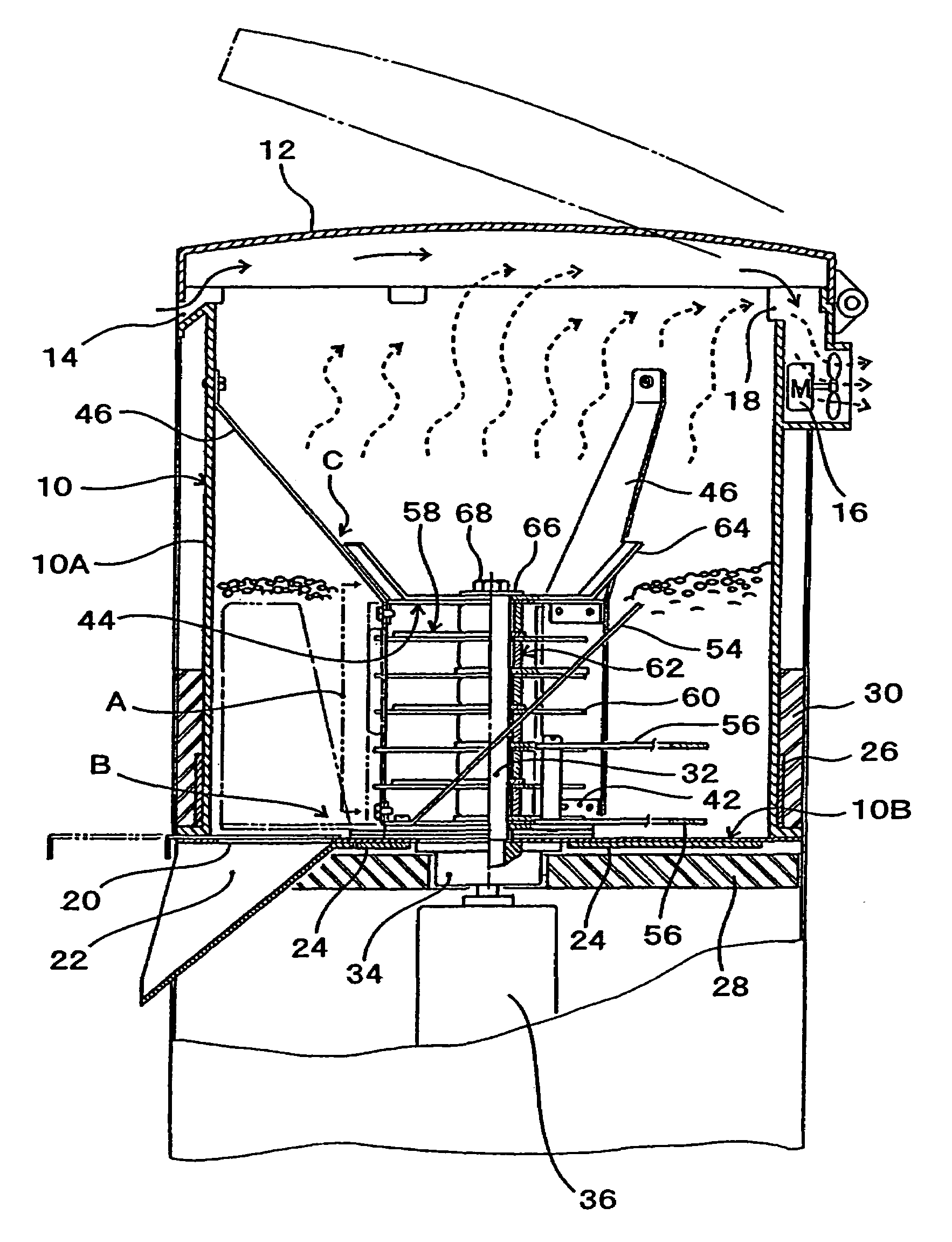
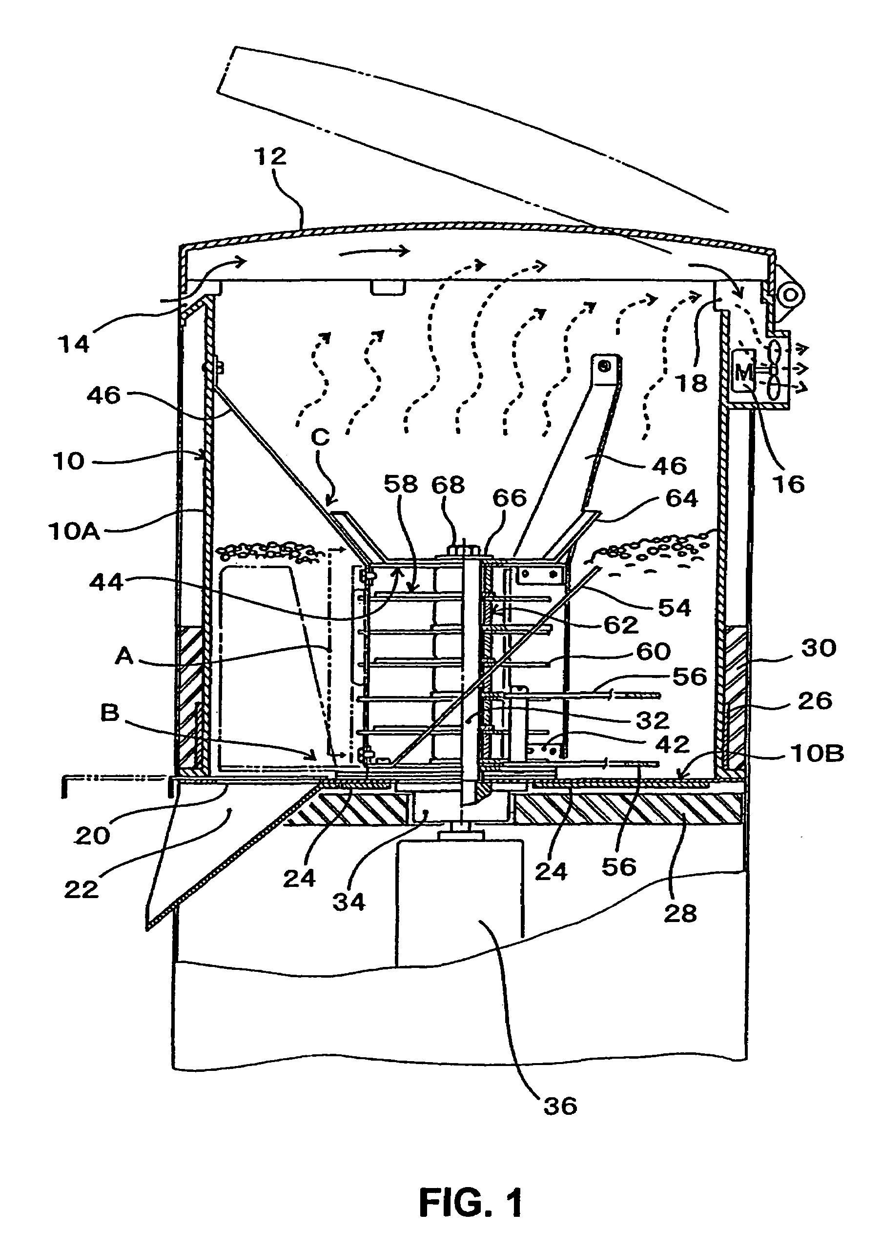
[0059]In FIGS. 1, 2 and 5, the reference numeral 10 indicates a cylindrical treatment tank which has a closed bottom. In the shown treatment tank, the bottom of the cylindrical section 10A is closed off by a bottom plate 10B, and a cover plate 12 is attached to the opening which is in the upper end portion of the cylindrical section 10A so that the cover plate 12 is opened and closed. The bottom plate 10B is made of a metal that is superior in terms of thermal conductivity, such as a stainless steel plate, etc. It is desirable that the cylindrical section 10A also be made of a similar material to that of the bottom plate 10B.

[0060]An intake opening 14 that admits outside air is provided in the upper portion of the treatment tank 10, and so are the exhaust fan 16 and exhaust passage 18 which are used to exhaust the vapor generated from the raw garbage. The draft of the exhaust fan 16 is set so that the vapor from the raw garbage does not condense inside the treatment tank 10. A catal...


PUM


Abstract

A raw garbage treatment apparatus including a treatment tank 10, a rotating shaft 32 which rises in an upright attitude from the center of the bottom of the treatment tank, a motor 36 which rotates the rotating shaft from beneath the treatment tank, a plurality of rotating blades 58 which have cutting vanes 58A that extend outward with the rotating shaft as the center and which are provided on the rotating shaft at intervals from each other, a plurality of fixed blades 60 through which the rotating shaft rotatably passes and which form a main cutter A together with the rotating blades, and a supporting frame 38 which has vertical plates 40 that hold the outer end portions of the fixed blades and whose upper end is fastened to the upper portion of the inside of the treatment tank.

Description

BACKGROUND OF THE INVENTION[0001]1. Field of the Invention[0002]The present invention relates to a raw garbage treatment apparatus that treats to dispose raw garbage such as food waste, leftover food, etc. while reducing the volume of such garbage by cutting and pulverizing the garbage, and it also relates to a cutter used in such a raw garbage treatment apparatus.[0003]2. Prior Art[0004]Biodegradation type apparatuses and drying type apparatuses have been known in the past as raw garbage treatment apparatuses. In the biodegradation system, degradation of organic matter is caused by microorganisms (bio-organisms), and various treatment units of this type have been commercially marketed for general household use. The drying system dehydrates and dries raw garbage by heating and agitating the garbage without relying on microorganisms.[0005]In the case of the biodegradation type system, apparatuses that have a slow degradation rate so that organic matter is slowly and naturally degrade...

Claims


Application Information

Patent Timeline
Patent Type & Authority Patents(United States)
IPC IPC(8): B02C18/12F26B11/14B02C18/16B02C18/18B09B3/00
CPCB02C18/0092B02C18/18B02C18/12B02C2018/188
Inventor OZAWA, TETSUYA
Owner IZUMI PROD CO
Why Eureka
Try Eureka