Eye characteristics measuring system

a measurement system and characteristic technology, applied in the field of eyecharacteristics measurement apparatuses, can solve the problems of double-path measurement, wide (large-diameter) beam, and difficult correct measurement,

Inactive Publication Date: 2006-07-06
KK TOPCON
View PDF3 Cites 18 Cited by
  • Summary
  • Abstract
  • Description
  • Claims
  • Application Information

AI Technical Summary

Benefits of technology

[0004] In apparatuses for measuring the optical characteristics of an eye under measurement having aberration, however, correct measurement is difficult in some cases due to much aberration. Especially, a secondary light source formed by collecting incident light on an eyeground

Problems solved by technology

In apparatuses for measuring the optical characteristics of an eye under measurement having aberration, however, correct measurement is difficult in some cases due to much aberration.
Especially, a secondary light source formed by collecting incident light on an eyeground has

Method used


Image

  • Eye characteristics measuring system
  • Eye characteristics measuring system
  • Eye characteristics measuring system

Examples


first embodiment

1. First Embodiment

(Optical-System Structure)

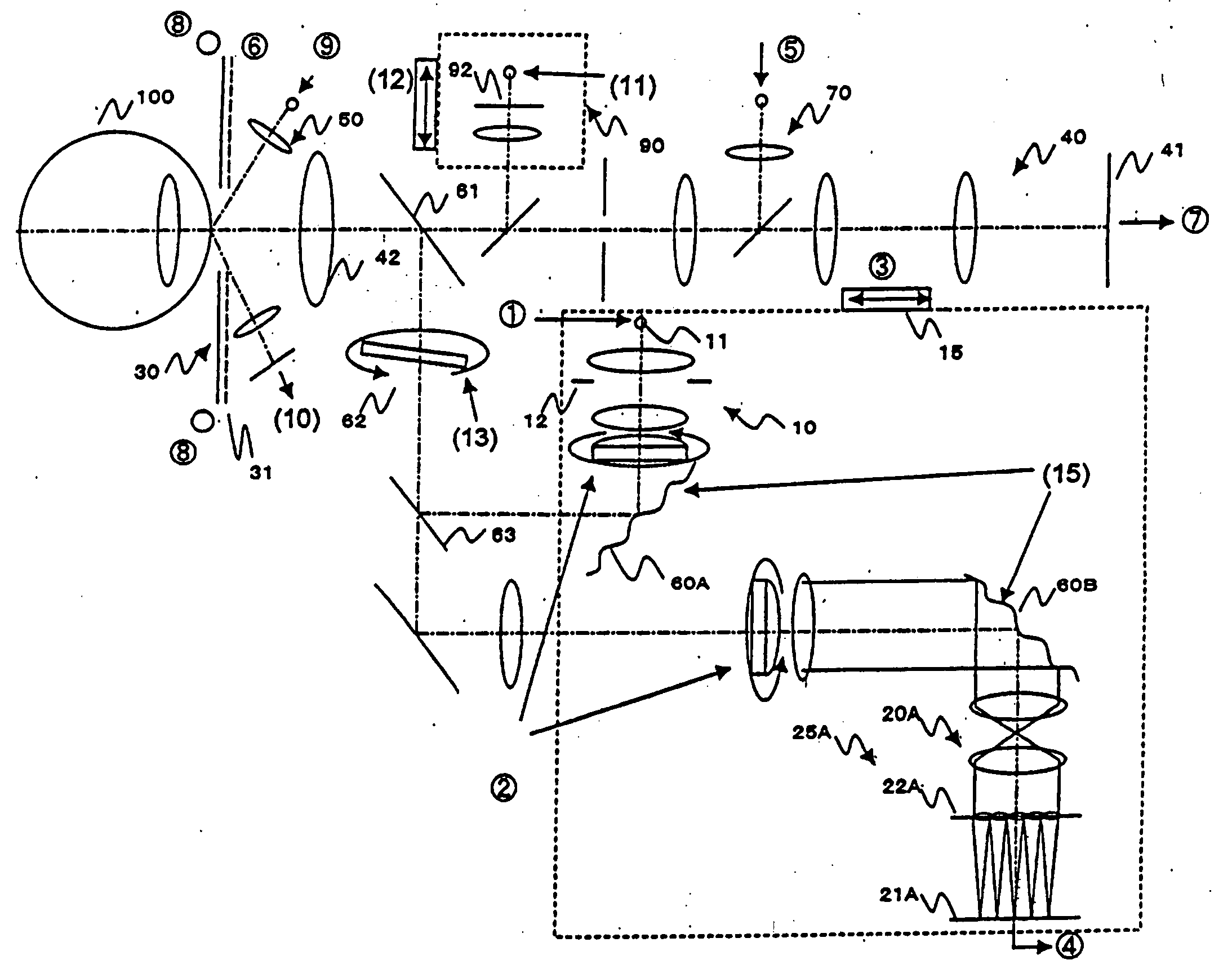
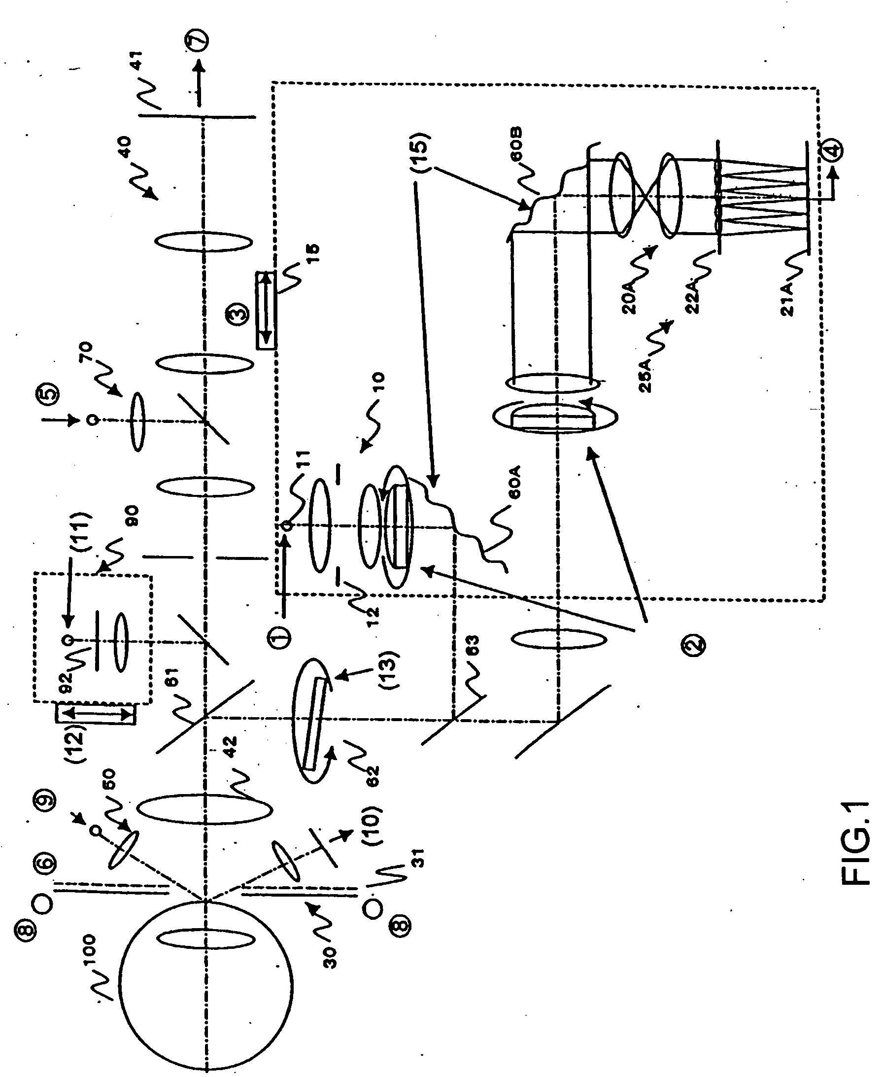
[0118]FIG. 1 is a view showing the structure of an optical system according to a first embodiment.

[0119] An eye-characteristics measurement apparatus includes a first illumination optical system 10, a first light-source section 11, a first measurement section 25A, an eye-front-part illumination section 30, an eye-front-part observation section 40, a first adjustment optical section 50, a first compensation optical section 60A, a second compensation optical section 60B, a second adjustment optical section 70, and an eyesight-target optical section 90. The first measurement section 25A has a first light-receiving optical system 20A and a first light-receiving section 21A. In an eye 100 under measurement, a retina (eyeground) and a cornea (eye-front part) are shown in the figure.

[0120] Each section will be described below in detail.

[0121] The first illumination optical system 10 illuminates a minute area on the eyeground of the eye 100 ...

second embodiment

2. Second Embodiment

(Optical-System Structure)

[0170]FIG. 7 is a view showing the structure of an optical system according to a second embodiment. FIG. 7 shows only a portion corresponding to that enclosed by the dotted line in FIG. 1, but the other portions are the same as those shown in FIG. 1. An eye-characteristics measurement apparatus shown in FIG. 7 further includes a second measurement section 25B having a short focal length, a low sensitivity, or a high density, and a beam splitter 23. A first conversion member 22A according to the present embodiment is a wavefront conversion member having a lens section with a long focal length or a high sensitivity. It is preferred that the second measurement section 25B be configured to have a short focal length, a low sensitivity, and a high density. The first conversion member 22A may be configured to have a long focal length and a high sensitivity.

[0171] The second measurement section 25B has a second light-receiving optical system ...

third embodiment

3. Third Embodiment

[0181]FIG. 9 is a view showing the structure of an optical system according to a third embodiment. FIG. 9 shows only a portion corresponding to that enclosed by the dotted line in FIG. 1, but the other portions are the same as those shown in FIG. 1. In the optical system shown in FIG. 9, a second compensation optical section 60B is inserted in common into first and second measurement sections 25A and 25B. A light beam reflected and returned from the retina of an eye 100 under measurement is led to the first and second measurement sections 25A and 25B through the second compensation optical section 60B. Since the optical beam is led to the second measurement section 25B through the second compensation optical section 60B, aberration obtained after compensation can be measured even in the second measurement section 25B. In addition, it is possible that the first and second compensation optical sections 60A and 60B are deformed until aberration measured at the output...


PUM


Abstract

The optical characteristics of an eye to be tested having a large amount of aberration can be measured accurately. A first illuminating optical system (10) illuminates an eye to be tested (100) with a wide beam by using a light flux from a light source (11). A first light receiving unit (21A) receives reflection light fluxes from the eye to be tested that have been converted into practically at least 17 beams by a first conversion member (22A). A first compensation optical unit (60A), disposed in the first illuminating optical system (10), compensates an illuminating light flux to the eye to be tested (100) for aberration. A second compensation optical unit (60B), disposed in a first light receiving optical system (20A), compensates a reflection light flux from the eye to be tested (100) for aberration. An operation unit determines, based on an output from the first light receiving unit (21A), a compensation amount for canceling out aberration to deform the first and second compensation optical units (60A, 60B) and hence compensate for aberration. In addition, the operation unit determines the optical characteristics of the eye (100), based on optical characteristics based on an output from the first light receiving unit (21A) after compensation, and on compensated optical characteristics.

Description

TECHNICAL FIELD [0001] The present invention relates to eye-characteristics measurement apparatuses, and more particularly, to an eye-characteristics measurement apparatus for precisely measuring the optical characteristics of an eye under measurement by using a wavefront sensor. BACKGROUND ART [0002] Recently, optical instruments used in the medical field have been spread. Especially in ophthalmology, optical-characteristics measurement apparatuses for checking eye functions such as the refraction and adjustment of eyes and the insides of eyeballs have been spread. For example, there exists a photorefractometer for obtaining the refractive power and the corneal shape of an eye under measurement. [0003] A retina-image resolution improving apparatus for compensating for wave aberration by deforming a compensation optical member similar to a deformable mirror has been disclosed (for example, in PCT Japanese Translation Patent Publication No. 2001-507258). In this apparatus, laser ligh...

Claims


Application Information

Patent Timeline
IPC IPC(8): A61B3/10A61B3/103A61B3/107A61B3/12
CPCA61B3/10A61B3/1005A61B3/1015A61B3/107A61B3/12
Inventor HIROHARA, YOKOYAMAGUCHI, TATSUO
Owner KK TOPCON
Why Eureka
Try Eureka