Segmented balloon catheter blade

a catheter blade and segmental technology, applied in the field of medical devices, can solve problems such as partial, or even complete, blockage of the artery, damage to the tissue that relies on the blood supply, and heart attack

Inactive Publication Date: 2006-03-14
BOSTON SCI SCIMED INC
View PDF67 Cites 81 Cited by
  • Summary
  • Abstract
  • Description
  • Claims
  • Application Information

AI Technical Summary

Benefits of technology

[0008]For the present invention, a device for incising a stenosis in the vasculature of a patient includes a plurality of blade segments that are mounted and aligned on a base member. The base member, in turn, is mounted on the external surface of an inflatable angioplasty balloon. Accordingly, when the balloon is inserted into the vasculature of a patient, positioned across a stenosis and subsequently inflated, the blade segments form an effective cutting edge that effectively conforms to the surface of the stenosis. Due to this ability of the cutting edge to conform with the peaks and valleys of the stenosis, the stenosis can be incised to a substantially uniform depth.

Problems solved by technology

The blockage of human arteries can lead to a variety of serious medical complications.
This is so because arterial blockages reduce blood flow through the affected artery and may result in damage to the tissue that is relying on the blood supply.
For example, if the blockage is in an artery which supplies blood to the heart itself, a heart attack may result.
This can result in a partial, or even complete, blockage of the artery.
Generally, however, the surface of a stenosis is bumpy and undulating, and contains numerous peaks and valleys.
As such, incision of a stenosis with one long, continuous blade that is mounted on the surface of an angioplasty balloon can be uneven.
Specifically, while the peaks of a stenotic surface may be effectively incised, incisions in the valleys present on the surface of the stenosis may be problematic.
Furthermore, long, continuous blades reduce the flexibility of the catheter making it more difficult to guide the catheter through the vasculature of the patient.

Method used


Image

  • Segmented balloon catheter blade
  • Segmented balloon catheter blade
  • Segmented balloon catheter blade

Examples


Embodiment Construction

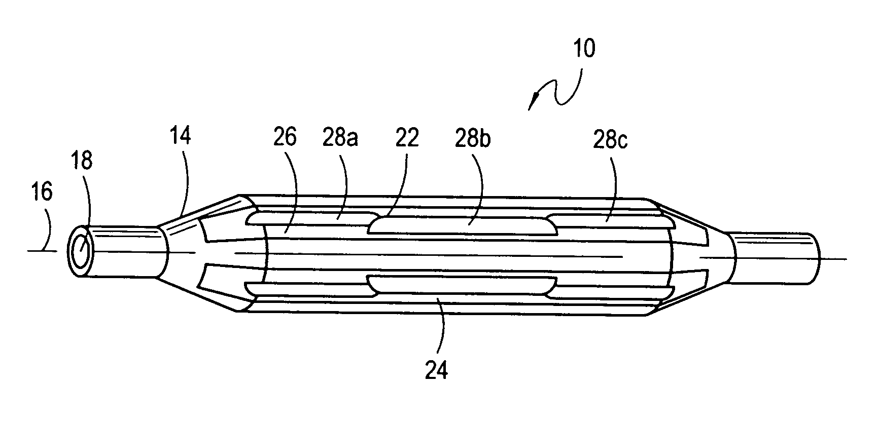
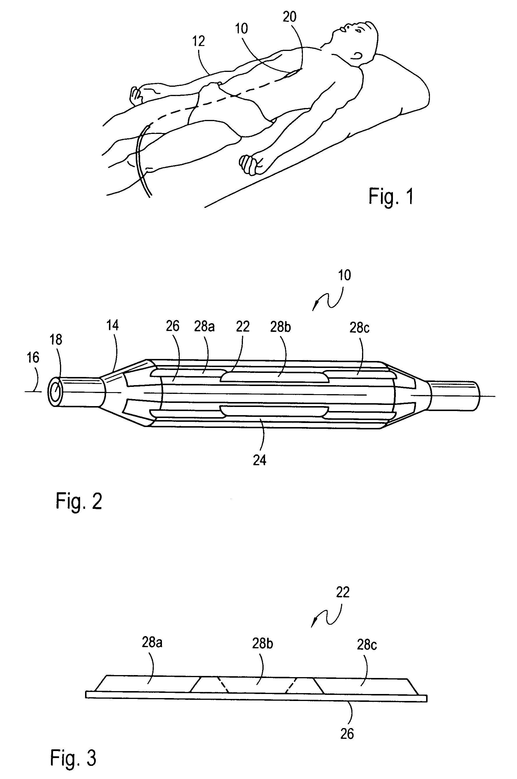
[0022]Referring initially to FIG. 1, a device 10 for incising and dilating a stenosis is shown positioned for operation inside a patient 12. As shown in FIG. 2, the device 10 includes an angioplasty balloon 14 that is elongated and defines a balloon axis 16. As shown, lumen 18 is provided to allow the balloon 14 to be tracked along a guidewire 20 (shown in FIG. 1) and to allow for inflation / deflation of the balloon 14. For the present invention, one or more blade units such as blade unit 22 and blade unit 24 are mounted on the external surface of the angioplasty balloon 14.

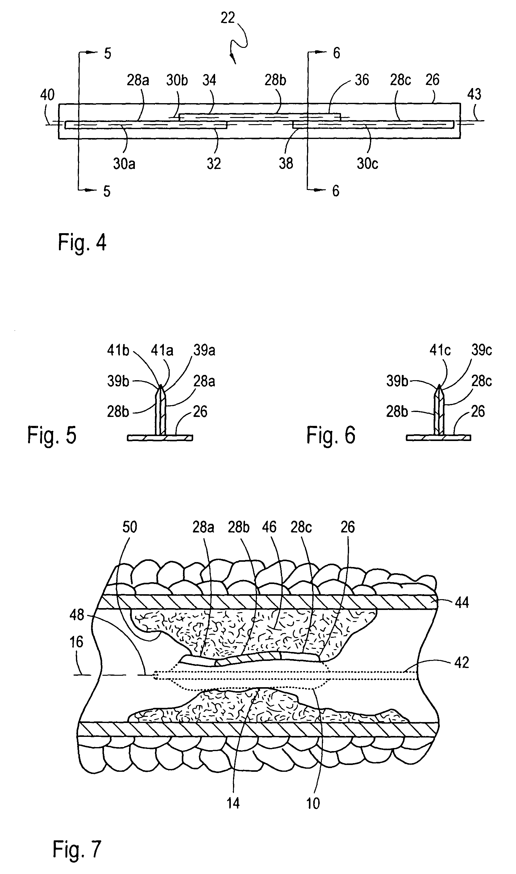
[0023]Referring now with cross reference to FIGS. 2, 3 and 4, it is to be appreciated that the blade unit 22 includes a base member 26 and a plurality of blade segments 28a, 28b and 28c. Although only three blade segments 28a, 28b, 28c are shown, it is to be appreciated that a blade unit 22 can contain any number of blade segments 28a, 28b, 28c for the present invention. Preferably, each blade segment 28a, 28b, 28...


PUM


Abstract

A device for incising a stenosis in the vasculature of a patient includes a plurality of blades mounted on a resilient base member. The blades are arranged in a pattern to allow for relative movement between adjacent blades. Specifically, at least one end portion of each blade is juxtaposed with an end portion of the next closest blade. The base member, in turn, is mounted on the external surface of an inflatable angioplasty balloon. When the balloon is inserted into the vasculature of a patient, positioned across a stenosis and subsequently inflated, the individually moveable blades form an effective cutting edge that conforms to the surface of the stenosis to effectively allow the stenosis to be incised to a substantially uniform depth.

Description

[0001]This application is a continuation of application Ser. No. 09 / 938,010, filed Aug. 23, 2001, now U.S. Pat. No. 6,632,231. The contents of application Ser. No. 09 / 938,010 are incorporated herein by reference.FIELD OF THE INVENTION[0002]The present invention relates generally to medical devices. More particularly, the present invention pertains to invasive surgical devices which are useful for the incision and dilation of a stenosis in the vasculature of a patient. The present invention is particularly, though not exclusively, useful for incising a stenosis with a balloon catheter blade to facilitate subsequent dilation of the stenosis.BACKGROUND OF THE INVENTION[0003]The blockage of human arteries can lead to a variety of serious medical complications. This is so because arterial blockages reduce blood flow through the affected artery and may result in damage to the tissue that is relying on the blood supply. For example, if the blockage is in an artery which supplies blood to t...

Claims


Application Information

Patent Timeline
Patent Type & Authority Patents(United States)
IPC IPC(8): A61B17/08A61B17/00A61B17/22
CPCA61B17/320725A61M2025/1086A61B2017/22061
Inventor RADISCH, JR., HERBERT R.
Owner BOSTON SCI SCIMED INC
Why Eureka
Try Eureka