Carbon nanotube sheet structure and method for its making

a carbon nanotube and sheet structure technology, applied in the field of carbon nanotubes, can solve the problems of large quantity of buckypapers that requires frequent change of filters, serious barriers to future practical applications of nanotube membranes, and inorganic chemistry, etc., to achieve the effect of improving separation or “peeling away, low basis weight and light weigh

Active Publication Date: 2019-02-14
GENERAL NANO LLC
View PDF5 Cites 6 Cited by
  • Summary
  • Abstract
  • Description
  • Claims
  • Application Information

AI Technical Summary

Benefits of technology

[0021]In another aspect of the invention, the continuous porous carrier material can also be a filter material that filters the dispersed CNTs from the liquid of the aqueous suspension of the CNTs. In this embodiment, the CNTs are filtered onto the continuous porous carrier material to form the CNT structure and CNT sheet, and the CNT sheet is then separated or peeled away from the continuous porous carrier material. In this embodiment, the CNT structure and CNT sheet will typically have a basis weight of CNTs sufficient to provide the CNT structure with integrity to be peeled away continuously from the carrier material as a free-standing CNT sheet, without tearing or degrading.
[0022]In a further aspect of the invention, a porous secondary layer can applied to an upper side of the continuous porous carrier material, before applying the CNT suspension. The secondary lay

Problems solved by technology

However, all the existing manufacturing techniques for nanotube membranes are discontinuous or batch processes and can only produce small quantities and very short membrane materials, which are serious barriers for future practical applications of nanotube membranes.
Current discontinuous or batch techniques can only produce nanotube membrane materials by filtering a nanotube suspension, and the dimensions are limited by the filter di

Method used


Image

  • Carbon nanotube sheet structure and method for its making
  • Carbon nanotube sheet structure and method for its making
  • Carbon nanotube sheet structure and method for its making

Examples


Embodiment Construction

[0051]As used herein, the terms “comprise,”“comprising,”“include,” and “including” are intended to be open, non-limiting terms, unless the contrary is expressly indicated.

[0052]As used herein, a “free-standing” sheet or structure of CNTs is one that is capable of formation, or separation from a filter material, and handling or manipulation without falling apart, or without significant flaking or crumbling of CNTs away from the sheet or structure.

[0053]A “continuous” sheet of material is an elongated sheet having a length that is orders of magnitude greater than the width of the sheet, and a roll of the sheet material.

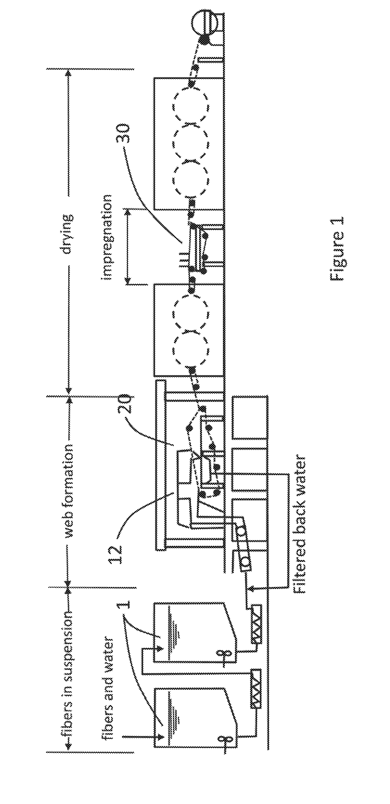
[0054]Conventional wet-laid nonwovens are made by a modified papermaking process. That is, the fibers to be used are suspended in water or other dispersive liquid. A specialized machine is used to separate the water or other dispersive liquid from the fibers to form a uniform sheet of material, which is then dried. The wet-laid process has its origins in the manufacture...


PUM

PropertyMeasurementUnit
Weightaaaaaaaaaa
Widthaaaaaaaaaa
Widthaaaaaaaaaa

Abstract

A carbon nanotube (CNT) sheet containing CNTs, arranged is a randomly oriented, uniformly distributed pattern, and having a basis weight of at least 1 gsm and a relative density of less than 1.5. The CNT sheet is manufactured by applying a CNT suspension in a continuous pool over a filter material to a depth sufficient to prevent puddling of the CNT suspension upon the surface of the filter material, and drawing the dispersing liquid through the filter material to provide a uniform CNT dispersion and form the CNT sheet. The CNT sheet is useful in making CNT composite laminates and structures having utility for electro-thermal heating, electromagnetic wave absorption, lightning strike dissipation, EMI shielding, thermal interface pads, energy storage, and heat dissipation.

Description

BACKGROUND OF THE INVENTION[0001]This invention relates generally to carbon nanotubes, and more particularly to methods for forming materials and structures from carbon nanotubes.[0002]The exceptional mechanical properties of carbon nanotubes can be used in the development of nanotube-based, high performance structural and multifunctional nanostructural materials and devices. Carbon nanotubes have been made that are nanometers in diameter and several microns in length, and up to several millimeters in length. Strong interactions occur between nanotubes due to the van der Waals forces, which may require good tube dispersion, good tube contact, and high tube loading in materials and structures formed from carbon nanotubes.[0003]Many applications, such as electrical conducting, thermal conducting and high performance nanocomposites, are made by pre-forming nanotubes into a network or membrane (5-200 μm in thickness) with controlled nanostructures (density, porosity, dispersion, alignme...

Claims


Application Information

Patent Timeline
IPC IPC(8): C01B32/168D04H1/4242B32B5/02B32B5/26D21H13/50D21H21/14
CPCC01B32/168D04H1/4242B32B5/022B32B5/26D21H13/50D21H21/14B32B2262/106B82Y40/00B82Y30/00H01B1/02H01B1/04B32B3/26B32B5/024B32B15/02B32B15/043B32B15/20B32B2255/02B32B2255/06B32B2255/205B32B2260/021B32B2260/046B32B2262/02B32B2262/0276B32B2262/101B32B2262/103B32B2262/105B32B2262/14B32B2264/02B32B2264/0214B32B2264/0264B32B2264/101B32B2264/102B32B2264/105B32B2264/107B32B2307/20B32B2307/212B32B2307/546B32B2307/718B32B2457/00B32B5/02B32B9/00C04B35/62218C04B35/62876C04B35/76C04B2235/3217C04B2235/3274C04B2235/408C04B2235/425C04B2235/5248C04B2235/526C04B2235/5288C04B2235/5296D04H1/732D21H21/52
Inventor JAYASINGHE, CHAMINDACHRISTY, LARRY ALLENCHAN, EDWARD MING
Owner GENERAL NANO LLC
Why Eureka
Try Eureka