
Reconfigurable modular microfluidic system and method of fabrication

a microfluidic system and modular technology, applied in the field of microfluidic system miniaturization, can solve the problems of unmet challenges for microfluidic developers, inability to test each section of the system in isolation, and difficulty in developing high efficiency, and achieve the effect of enhancing the usability of the breadboard system and maximising the configuration efficiency

Active Publication Date: 2006-03-14
RHEONIX
View PDF33 Cites 20 Cited by
  • Summary
  • Abstract
  • Description
  • Claims
  • Application Information

AI Technical Summary

Benefits of technology

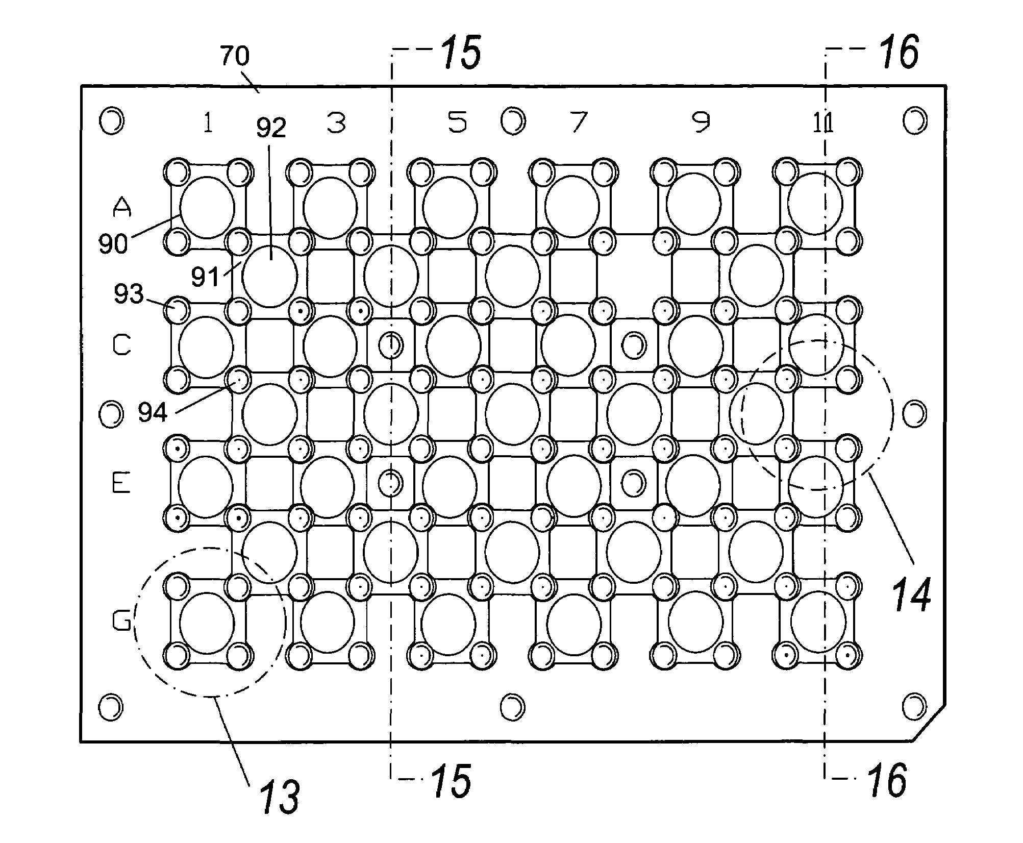
[0022]According to this invention, the combination of pre-fabricated pockets for chip alignment, overlapped corner fluid communication port, on-chip sealing means and the flexibility of egress or ingress of a fluid at any fluid communication port provides true chip-level reconfigurability and reusability that is not realized in existing technologies. Upon the completion of or during an investigation, any of the components of the fluid network can be released, replaced or repositioned without disturbing the surrounding components in the system. This arrangement therefore provides the maximum configuration efficiency by keeping the complete assembled fluid network undisrupted during the replacement of the chips and complete network flexibility in that each component of the fluid system can be independently replaced and tested.
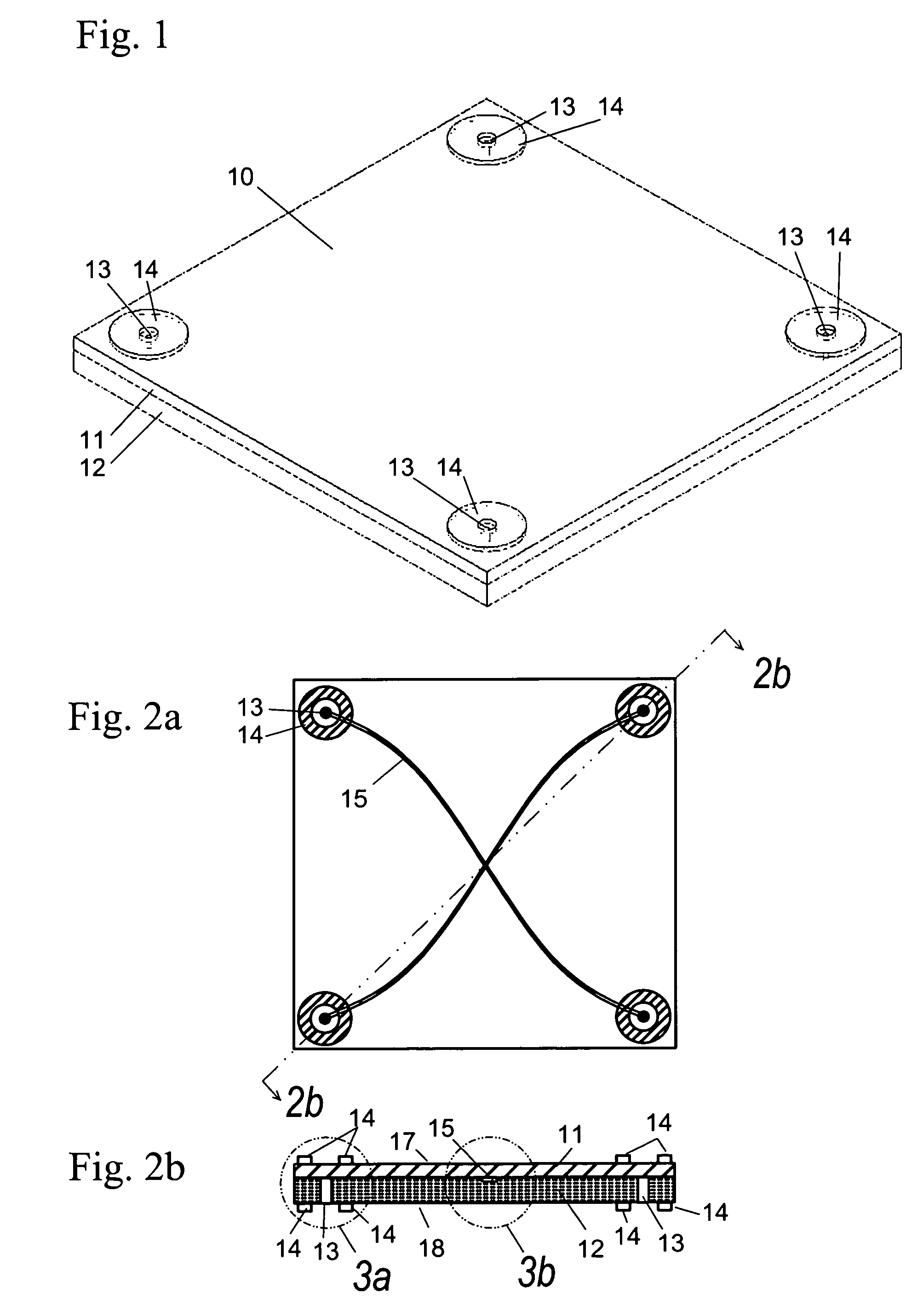
[0023]A further embodiment of this invention is that the system provides optical access for fluid visualization or molecular detection on each chip. For any microfluidic application development work, optical access to the fluidic channels is of paramount importance for microscopic or unaided visual inspection, ultraviolet detection or other means. To provide the maximum optical accessibility, the present invention incorporates a perforated cover and base plates to hold microfluidic chips. Each chip preferably includes an optically transparent cover lid. When the chip is positioned in the base plate, the optically transparent side is aligned atop or beneath a viewing window to allow free optical access. This configuration greatly enhances the usability of the breadboard system described herein.
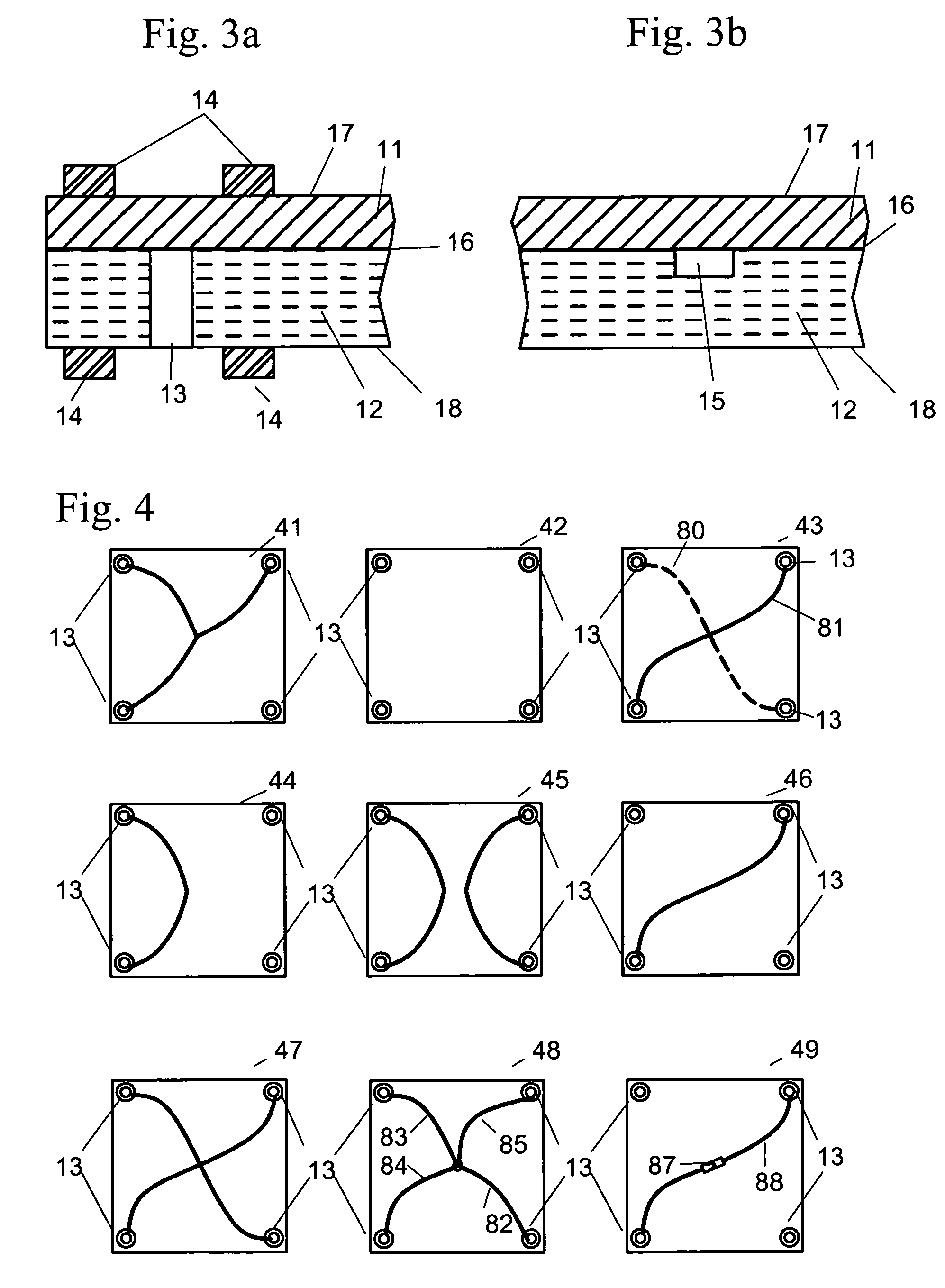
[0024]In order to establish unrestricted fluid ingress or egress at arbitrary fluid communication ports upon system assembly, the present invention provides a means for chip-based fluid connection. In one preferred embodiment, the fluid connection chip is constructed by a particular connecting pattern between the fluid communication ports situated at each corner of the chip to a group of capillaries located in the center. For a chip with four corner fluid communication ports, there are five unique patterns to cover all possible fluid delivery combinations. The five fluid communication chips thus provide a novel modular and reusable fluid ingress or egress method.

Problems solved by technology

However, there are inherent difficulties for developing high efficiency, fully integrated microfluidic applications.
On the other hand, it is often impossible to test each section of a system in isolation before attempting integration; many components do not provide meaningful information until they are assimilated into the system as a whole.
The demand to isolate the specific impact of an individual module in a sequential operation in addition to the ability to investigate the overall performance for the integrated device present an unmet challenge for microfluidic developers.
However, unlike electronics, there is no standardization of discrete microfluidic components which lend themselves to easy breadboarding, as do the standardized components and packaging of electronic components.
Also, the routing of fluids encounters difficulties that are not presented when conducting electrons through wires in electronic circuits.
Currently, the limited options to join discrete microfluidic components to form fluidic network are almost exclusively based on using epoxy with standard capillaries or “Nanoport” fittings made by Upchurch Scientific, a division of Scivex, Oak Harbor, Wash.
While the former method is straightforward and widely utilized by many researchers, its cumbersome nature during the capillary and system assembly makes the process very tedious and time consuming.
The length of capillary required to make connections increases the overall system length, resulting in higher flow resistances and difficulty when balancing the flow in parallel branches of a system.
The complexity of such a capillary network scales up rapidly such that even in the integration of a modest number of microfluidic components, the “plumbing” would become excessively complex.
Additionally, the components used in an assembled system are not readily reusable.
Although the fittings that Upchurch Scientific provides are relatively small, in comparison to the chip scale devices to which they attach, they require a bonding area that can exceed the active device area of the fluidic chip.
For this reason, there can be difficulties with obscuring the optical access to the active area of the chip.
However, the stacking of chips, while making the sealing of the components simpler, eliminates the investigator's ability to monitor the system optically.
The stacked scheme also restricts fluid delivery by limiting the available locations for ingress or egress.
This scheme necessitates adherence to a set base pattern; the flexibility of the system is restricted by the “motherboard” design.
The base pattern is predefined and limits the overall microfluidic network configurability.

Method used


Image

  • Reconfigurable modular microfluidic system and method of fabrication
  • Reconfigurable modular microfluidic system and method of fabrication
  • Reconfigurable modular microfluidic system and method of fabrication

Examples


Embodiment Construction

[0042]The present invention addresses the need for rapidly building an application specific microfluidic chemical analysis system from standardized components.

[0043]The system of the invention is constructed from a multiplicity of discrete modular microfluidic devices or “chips”, assembled on an alignment base (“breadboard”). The chips are standardized as to shape, size and thickness, allowing great flexibility in assembly of the chips as needed.

Module / Chip Structure

[0044]In one embodiment of the invention, the chips (microfluidic modules) are essentially square in layout, with a fluid passage or hole (fluid communication port) located at each corner of the chip, surrounded by a sealing feature. The square layout of the chip allows the chips to be arranged in a diagonal array, meaning only one corner of adjacent chips overlap. The diagonal array permitted by this arrangement of square chips and four corner holes gives the ability to branch the fluid path without making special provi...


PUM

PropertyMeasurementUnit
Lengthaaaaaaaaaa
Pressureaaaaaaaaaa
Shapeaaaaaaaaaa

Abstract

A reconfigurable modular microfluidic system, providing a microfluidic breadboard platform for the formation of fluidic network and fluidic sealing upon a system assembly. Modular microfluidic elements or “chips” are arranged on a precisely machined alignment base to form a fluidic network, with fluid connections provided directly from chip-to-chip at overlapping corners. Fluidic access to external devices is possible at every fluid connection and through special ingress / egress chips. By maintaining a largely planar layout, optical access is provided for detecting or visualization for every chip. The assembly may be covered by a perforated cover plate.

Description

REFERENCE TO RELATED APPLICATIONS[0001]This application claims an invention which was disclosed in Provisional Application No. 60 / 470,760, filed May 15, 2003, entitled “RECONFIGURABLE MODULAR MICROFLUIDIC SYSTEM AND METHOD OF FABRICATION”. The benefit under 35 USC § 119(e) of the United States provisional application is hereby claimed, and the aforementioned application is hereby incorporated herein by reference.BACKGROUND OF THE INVENTION[0002]1. Field of the Invention[0003]The invention pertains to the field of miniaturized chemical and biochemical fluid management systems using microfluidic technology. In particular, the invention relates to the design and fabrication of reconfigurable microfluidic systems using discrete devices and other building blocks on a “breadboard” base.[0004]2. Description of Related Art[0005]The concept of the breadboard is well known to those familiar with electronics and electronic circuits. The term “breadboard” derives from the earliest days of elect...

Claims


Application Information

Patent Timeline
IPC IPC(8): B01L3/02B01L11/00B01L3/00G01N15/06G01N21/00B01L9/00B01L99/00G01N30/60
CPCB01L9/527B01L3/502715B01J2219/0081Y10T29/49B01L2200/025B01L2200/027B01L2200/028B01L2300/043B01L2300/0816B01L2300/0829B01L2300/0861B01L2300/0874G01N30/6082G01N30/6095Y10T436/11Y10T436/118339Y10T29/49002Y10T436/117497G01N30/74G01N30/6047G01N2030/8881
Inventor ZHOU, PENGYOUNG, LINCOLN
Owner RHEONIX
Learn More