Modulated laser light detector

a laser light and detector module technology, applied in the field of laser light detectors, can solve the problems of noise on the incoming sine wave, unstable elevation indication, and/or correlator approach of the '617 patent, and achieve the effects of accurate detection of the peak value of laser light signals, low noise characteristics, and reliable measurement of peak magnitudes

Active Publication Date: 2006-03-14
TRIMBLE NAVIGATION LTD
View PDF52 Cites 47 Cited by
  • Summary
  • Abstract
  • Description
  • Claims
  • Application Information

AI Technical Summary

Benefits of technology

[0010]Accordingly, it is an advantage of the present invention to provide a modulated laser light detector that can reliably measure the peak magnitudes of received laser light signals at their respective photocells, and thereby reliably indicate the correct grade or elevation where the laser signal impacts the receiver photocell elements.
[0011]It is another advantage of the present invention to provide a modulated laser light receiver that can detect the relative magnitudes or strengths of the laser light impacting at least two photocell elements of the receiver unit, while using a synchronous rectifier circuit having low noise characteristics to more accurately detect the peak values of the laser light signals impacting the photocells.
[0012]It is a further advantage of the present invention to provide a modulated laser light detector that uses a synchronous rectifier circuit having low noise characteristics to detect the relative strengths of laser light beams impacting at least two photocells, in which two synchronous rectifiers use multiple-input multiplexers to synchronously control amplifiers having low noise characteristics and will more accurately measure the relative strengths of the incoming signals from the at least two photocells.
[0013]It is yet another advantage of the present invention to provide a modulated laser light detector that uses a pair of synchronous rectifier circuits to detect the relative strengths of laser light signals impacting at least two photocells of the receiver unit, while having the ability to use several different photocell arrangements to produce at least two channels of input signals that will be signal conditioned and directed to the synchronous rectifiers.
[0014]Additional advantages and other ...

Problems solved by technology

This auto-correlator approach of the '617 patent exhibits certain problems.
One inherent problem is noise on the incoming sine wave.
Therefore, the capacitor voltage will be incorrect, and this will result in elevation errors, and/or unstable elevation indications.
Another inherent problem of this particular circuit design is that the sampled voltage that is placed on the capacitor will discharge over time into the ratio comparator 111.
One implementation problem with the...

Method used


Image

  • Modulated laser light detector
  • Modulated laser light detector
  • Modulated laser light detector

Examples


Embodiment Construction

[0027]Reference will now be made in detail to the present preferred embodiment of the invention, an example of which is illustrated in the accompanying drawings, wherein like numerals indicate the same elements throughout the views.

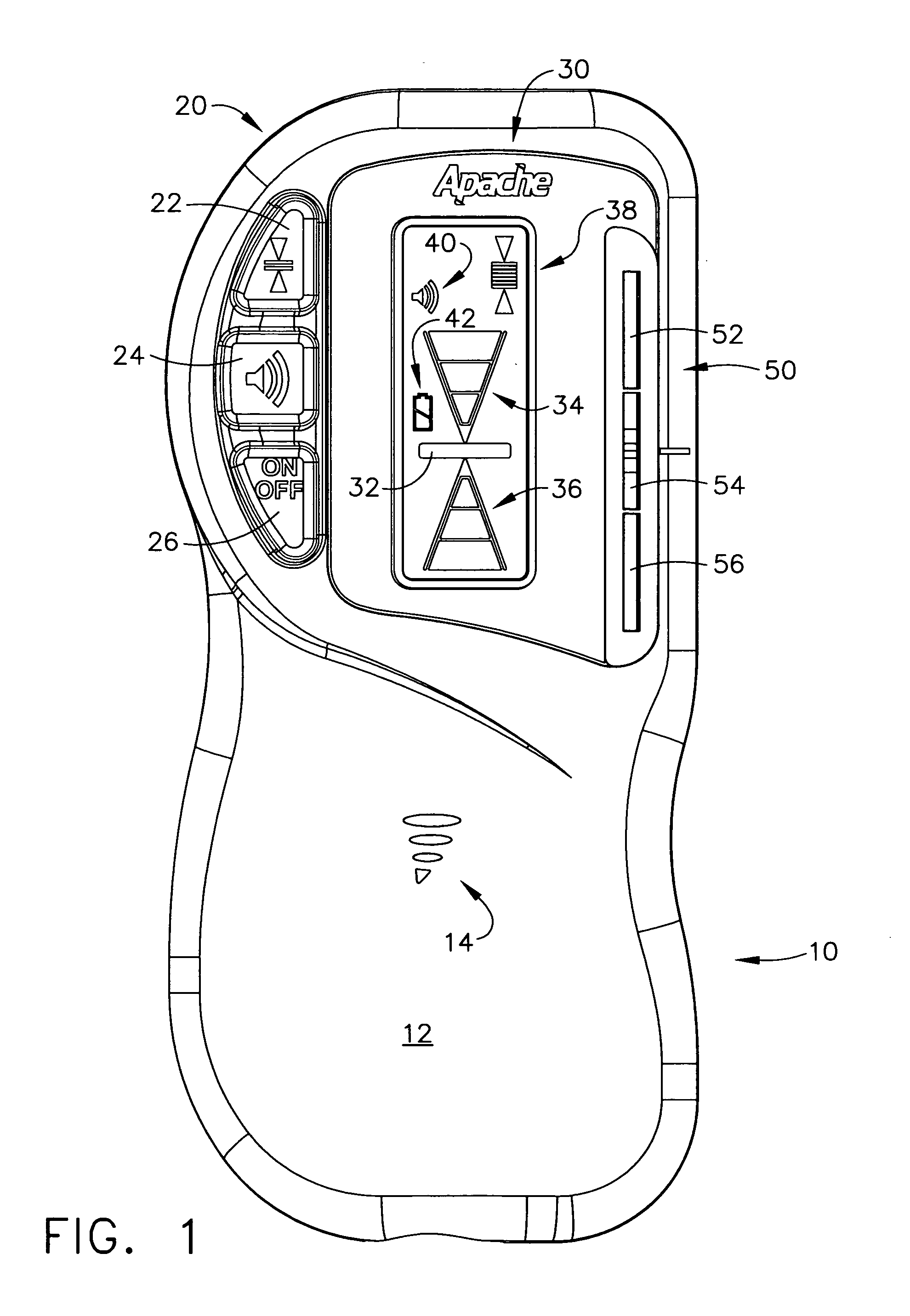
[0028]Referring now to FIG. 1, a modulated laser beam detector unit is illustrated, generally designated by the reference numeral 10. Its front outer surface at 12 is typically a plastic molded housing, which has some openings at 14 to allow for an internal beeper or other type of audio output device to be used. A set of pushbutton switches generally designated by the reference numeral 20 are located along the upper left-hand side of the case. These switches are designated by the reference numerals 22, 24, and 26, in which the top switch 22 acts as a dead band control switch, the middle switch 24 enables the beeper (or other type of audio output device) to be activated, and the bottom switch 26 is the unit's ON-OFF switch.

[0029]The modulated laser beam de...


PUM


Abstract

A modulated laser light detector that converts laser light energy into electrical signals which exhibit a frequency that is substantially the same as the laser light modulation frequency, in which these signals allow the detector unit to determine a position where the laser light is impacting upon a photodiode array. A synchronous rectifier circuit is provided which, by use of a phase locked loop, converts a full-wave analog signal representative of the modulated laser energy into a half-wave analog signal, which is filtered and demodulated to generate a DC level that is indicative of the strength of the received laser light energy. At least two channels of these signals are used to determine the impacting position of the laser light energy.

Description

TECHNICAL FIELD[0001]The present invention relates generally to laser light detectors and is particularly directed to laser light detectors of the type which detect modulated laser light energy. The invention is specifically disclosed as a modulated laser light detector that converts laser light energy into electrical signals which exhibit a frequency that is substantially the same as the laser light modulation frequency, and then signal conditions the electrical signals in a manner that allows the detector unit to determine a position where the laser light is impacting upon a photodiode array. A synchronous rectifier circuit is provided which, by use of a phase locked loop, converts a full-wave analog signal representative of the modulated laser energy into a half-wave analog signal, which is filtered and demodulated to generate a DC level that is indicative of the strength of the received laser light energy. At least two channels of these signals are used to determine the impactin...

Claims


Application Information

Patent Timeline
IPC IPC(8): H03F3/08
CPCH03F3/08G01C15/006
Inventor AKE, DUWAIN K.
Owner TRIMBLE NAVIGATION LTD
Why Eureka
Try Eureka