Synchronous, clocked communication system with relative clock and method for configuring such a system

Active Publication Date: 2006-03-14
SIEMENS AG
View PDF10 Cites 16 Cited by
  • Summary
  • Abstract
  • Description
  • Claims
  • Application Information

AI Technical Summary

Benefits of technology

[0013]The next preferred embodiment of the invention is characterized by the fact that data which are intended for the device to be controlled, before they are transmitted to the decentralized input/output module, are provided by the control unit with a stamp which is composed of a relative time referenced to the time of the planned signal output and an output switching event. The data with this stamp are transmitted to the input/output module via the data network, the relative time, as part of the stamp, consisting of two parts, one part determining the communication cycle of the communication system in which the signal output is to take place and the other part determining the time relative to the start or to the end of the communication cycle of the communication system in which the signal output is to take place. The data which are provided with such a stamp relates to the planned signal output and are intended for the device to be controlled are converted by the decentralized input/output module into signals which can be interpreted for the device to be controlled and are switched in accordance with the predetermined switching event at the output of the decentralized input/output module at the time which is predetermined by the transmitted stamp and are output to the device to be controlled. This embodiment is of particular advantage in that the switching of an output event at the output of the decentralized input/output module can be planned precisely and carried out with extraordinary precision depending on the time of registration of an entry event at the input of a decentralized input/output module. This is extraordinarily advantageous in the field of drive engineering in distributed automation systems, for example in the case of wood-processing machines, or for the switching of cams etc. The time interval between input event and output event is thus individually adjustable and achievable in each case with the same high accuracy in time for any situation in the field of application described, hence the dependence on dead times of affected stations in the communication system is also greatly reduced. Thus, an isochronous data exchange or, control of events, or event sequences within the communication system between the stations can be made possible, or considerably improved on the basis of these embodiments.
[0014]A further preferred embodiment of the present invention is characterized by the fact that the switching and forwarding of signals to a device to be controlled takes place at the output of a decentralized input/output module in defined dependence, which is adjustable in time, relative to the time of registration and detection of signals of a device to be controlled at the input of a decentralized input/output module. The particular advantage of this form lies in that, as a result, applicative event sequences can be implemented which, in particular, are of eminent significance especially in the case of wood-processing machines, for example in the productio

Problems solved by technology

However, it is not possible at present to introduce a relative clock which is valid for such a system, and to the respective valid relative time of which all stations connected to the co

Method used


Image

  • Synchronous, clocked communication system with relative clock and method for configuring such a system
  • Synchronous, clocked communication system with relative clock and method for configuring such a system
  • Synchronous, clocked communication system with relative clock and method for configuring such a system

Examples


Example

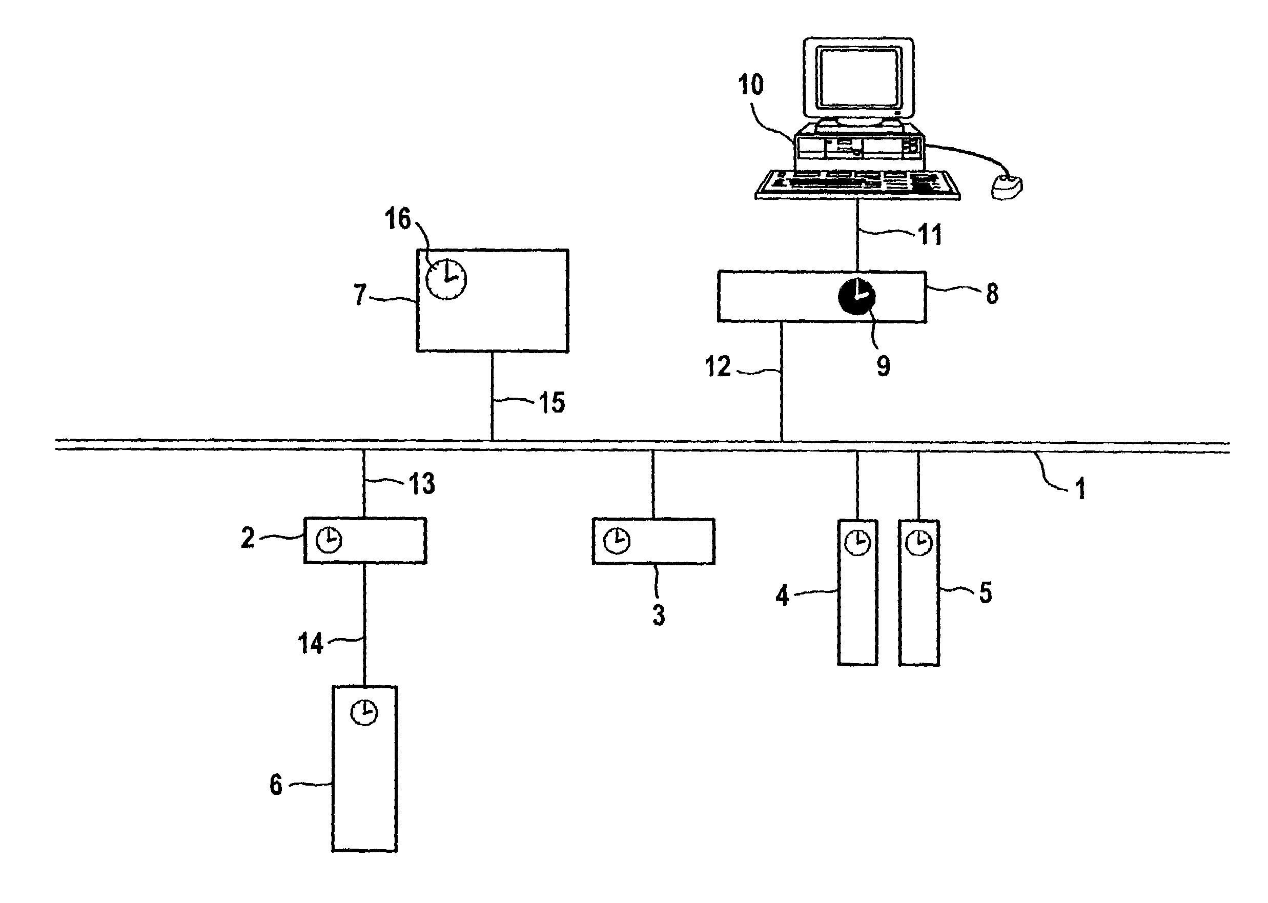
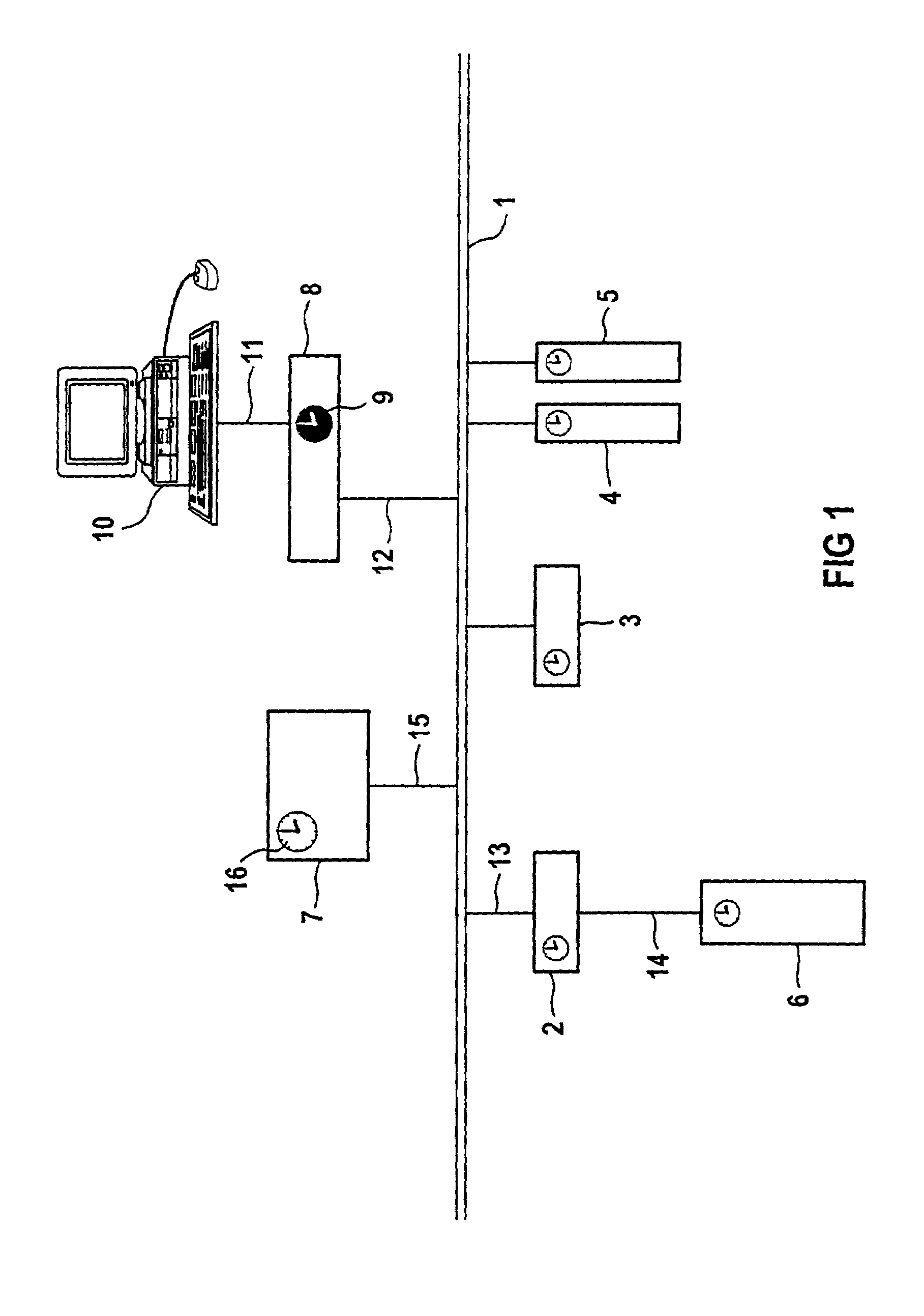
[0022]FIG. 1 shows a diagrammatic representation of an exemplary embodiment of a synchronous, clocked communication system with relative clock. The communication system shown is, at the same time, a distributed automation system. In the text which follows, these two terms will be used synonymously. The exemplary embodiment shown consists of a number of stations which can be formed both as transmitter and as receiver, at the same time, and thus can transmit and also receive both signals or data. All stations are connected directly or indirectly to the data network 1, for example by a bus system with and / or without real-time characteristics such as clock synchronization and equidistance such as, e.g. Ethernet, industrial Ethernet, field bus, professional field bus, FireWire or also internal PC bus systems (PCI) etc., but also clocked data networks such as, for example, isochronous real-time Ethernet, via data lines of which only data lines 11, 12, 13, 14 and 15 have been shown for rea...


PUM


Abstract

The invention relates to a synchronous, clocked communication system, for example a distributed automation system, the stations of which can be arbitrary automation components which are coupled to one another via a data network (1) for the purpose of mutual data exchange. In this arrangement, all possible bus systems such as, e.g. field bus, professional field bus, Ethernet, industrial Ethernet etc. are available for use as the data network (1) of the communication system. One station of this communication system is designated as timing generator and ensures the distribution and maintenance of the communication clock used to and by all stations. The timing generator can also introduce a relative clock (9) in the entire communication system at all stations via the same mechanism. This station is thus also the master of the relative clock (9) or the applicable relative time (16). All stations of the communication system are, therefore, continuously synchronized to the relative clock (9), which is applicable throughout this system, with the valid relative time (16) and, therefore have the same understanding of time at any time. This distinctly improves or even makes possible, respectively, the implementation of applicative sequences, synchronization of events occurring simultaneously, accuracy in time during the detection of events or, respectively, switching of outputs.

Description

FIELD OF THE INVENTION[0001]The invention relates to a synchronous, clocked communication system with relative clock and a method for configuring such a system.BACKGROUND OF THE INVENTION[0002]A synchronous, clocked communication system having characteristics of equidistance is understood to be a system of at least two stations which are connected to one another via a data network for the purpose of the mutual exchange of data or, the mutual transmission of data. In this arrangement, the data exchange is cyclic in equidistant communication cycles which are predetermined by the communication clock used by the system. Stations are, for example: centralized programmable controllers; programming, configuration or operating devices; peripheral devices such as e.g., input / output modules, drives, actuators, sensors, stored-program controllers (SPS) or other control units, computers or machines which exchange electronic data with other machines, particularly those which process data of othe...

Claims


Application Information

Patent Timeline
IPC IPC(8): H04L7/00G06F1/14H04J3/06
CPCH04J3/0652G06F1/14
Inventor FRANKE, MICHAELHEIDER, ALEXANDERKIESEL, MARTIN
Owner SIEMENS AG
Why Eureka
Try Eureka